OrCAD Configuration and Tips
Note: This article is based on Cadence OrCAD Capture CIS.
Basics
To draw schematic diagrams, use OrCAD Capture CIS (Start Menu -> Cadence -> Capture CIS). To design PCBs, use Allegro PCB Designer (Start Menu -> Cadence -> PCB Editor).
In general, using a .DSN file is sufficient to encompass the entire project. Opening it will automatically generate .opj and other schematic files. If you are using Git for version control, you can add the following to your .gitignore:
# From the original gitignore

#############
## Allegro
#############

# Ignore log file
*.log
*.log,1
*.log,2
*.log,3

*.dml
*.lst

# Ignore recording of Allegro events
*.jrl
*.jrl,1

*.tag

# Report files
*.rpt

# Report files
*.cfg
*.cfg,1

*.lck

# Report files
*.txt
*.txt,1
*.txt,2

# Exclude XY data
!place_txt.txt

# DXF import files
*.cnv

# Exclude Gerber param file
!art_param.txt

# Folder
# Exclude the entire folder
/signoise.run/

#############
## OrCAD
#############
*.dbk
*.opj
*.DRC
*.DSNlck

# Ignore netlist
allegro/
Settings
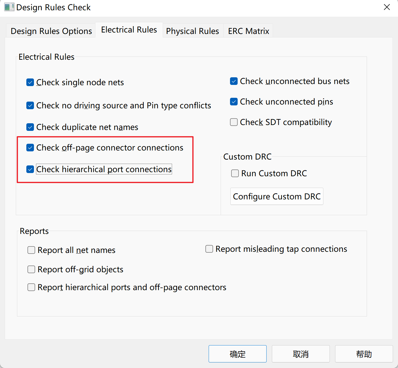
DRC Settings:

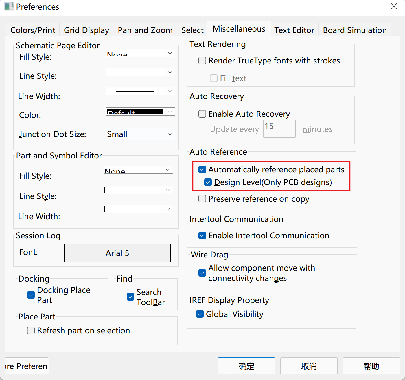
Automatically rename reference designators when copying components:

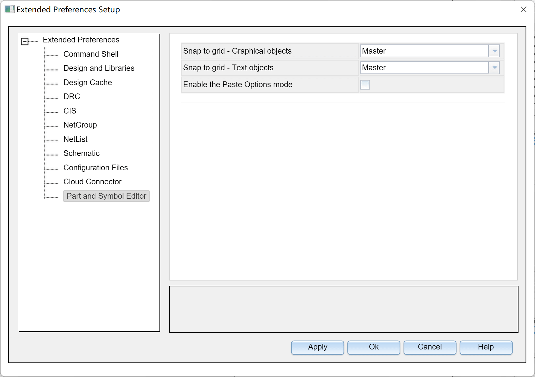
Snap components to grid while moving text:

Note: When using the CIP library and encountering the message "not found in the configured library lists," check for spaces in the file path.
- Mouse Wheel Zoom:
Options-Preferences...-Pan and Zoom- Set bothZoom Factorvalues to 1.1x - Refresh Schematic While Placing Components:
Options-Preferences...-Miscellaneous-Place Part– Check "Refresh part on selection" - Set Grid Spacing:
Options-Preferences...-Grid Display-Grid Spacing- Set it to 1/2
Keyboard Shortcuts
- Draw Wire:
W - Cancel:
ESC - Drag Bus:
F4 - Place Net Label:
N - Rotate / Flip Horizontally / Flip Vertically:
R/H/V - Open CIS Panel:
Z - Place Power / Ground:
F/G - No Connect:
X - Filter:
Ctrl+I - Select Multiple Elements: Hold
Ctrland click to select - Copy and Auto Increment Reference Designators: Hold
Ctrland drag components - Move Schematic Around with Mouse as Pivot: Hold
Cand drag the mouse - Place Bus:
E - Place Text:
T
Errors and Solutions
- Unable to Drag Components: Generally, restarting can resolve this issue.
Tips
Difference Between Off-Page and Port
Off-page is generally used for flat schematic diagrams, while port is typically used for hierarchical schematic diagrams.
DRC Check
1. انقر على شجرة الملفات واختر المشروع بأكمله.
2. انقر على شريط الأدوات `الأدوات` - `فحص قواعد التصميم...`
3. حدد الخيارات التالية: `تشغيل القواعد الفيزيائية` و `عرض النتائج`
4. انقر على "موافق"، سيتم إنشاء تقرير وفتحه تلقائياً.

## الإشارات والشكر

- [【دليل بداية سريع لـ Cadence】](https://blog.csdn.net/ReCclay/article/details/101225359)
- [البرنامج التعليمي لـ OrCAD Capture](https://resources.orcad.com/orcad-capture-tutorials)
- [حلاً لمشكلة ضبابية الخطوط في برنامج Cadence على أجهزة الكمبيوتر ذات شاشات عالية الدقة](https://blog.csdn.net/qq_34338527/article/details/108846792)
تمت ترجمة هذه المشاركة باستخدام ChatGPT، يرجى تزويدنا بتعليقاتكم إذا كانت هناك أي حذف أو إهمال.