EMC Design for Signal Ground and Chassis Ground
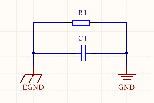
Typically, in the context of PCB design, when connecting signal ground and chassis ground, we employ a parallel connection of a high-voltage capacitor (1~100nF/2kV) and a large resistor (1MΩ). This serves to enhance EMC (Electromagnetic Compatibility) performance.
The capacitor's function is to allow AC signals to pass while blocking DC signals. From an EMI (Electromagnetic Interference) perspective, this arrangement directs high-frequency interference generated within the circuit into the chassis ground, preventing it from creating antenna radiation. From an EMS (Electromagnetic Susceptibility) perspective, it can suppress transient common-mode voltage differences between high-frequency interference sources and the circuit. This is particularly important when direct connections are either not possible or not sufficiently safe, for instance, when connecting the GND after a 220VAC rectifier bridge to the chassis ground.
The resistor serves to discharge accumulated charge, thereby safeguarding the circuit from ESD (Electrostatic Discharge) damage. If only a capacitor connects the signal ground and chassis ground, the signal ground remains floating. During ESD testing, the signal ground can gradually accumulate a high-voltage charge. Once this voltage exceeds what the nearest ground connection can tolerate, an electrical discharge arc occurs, resulting in a significant current surge within nanoseconds, which can damage the circuit. By incorporating this resistor in parallel, the charge can be slowly dissipated.
References and Acknowledgments
Original: https://wiki-power.com/ This post is protected by CC BY-NC-SA 4.0 agreement, should be reproduced with attribution.
This post is translated using ChatGPT, please feedback if any omissions.