Basic Components - Transistors
A transistor is a component that controls current with current.
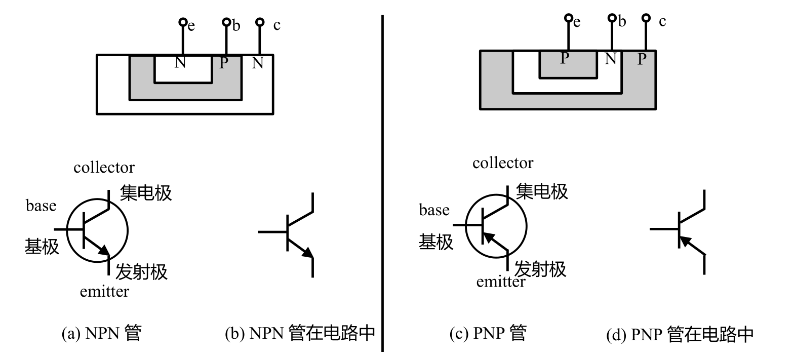
Differentiating Polarities
Apart from the base, the one with an arrow is the emitter, and the one without is the collector. An arrow pointing outwards represents NPN, while an arrow pointing inwards represents PNP.
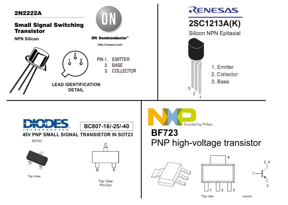
Identifying Different Package Pins
Basic Current Relationships
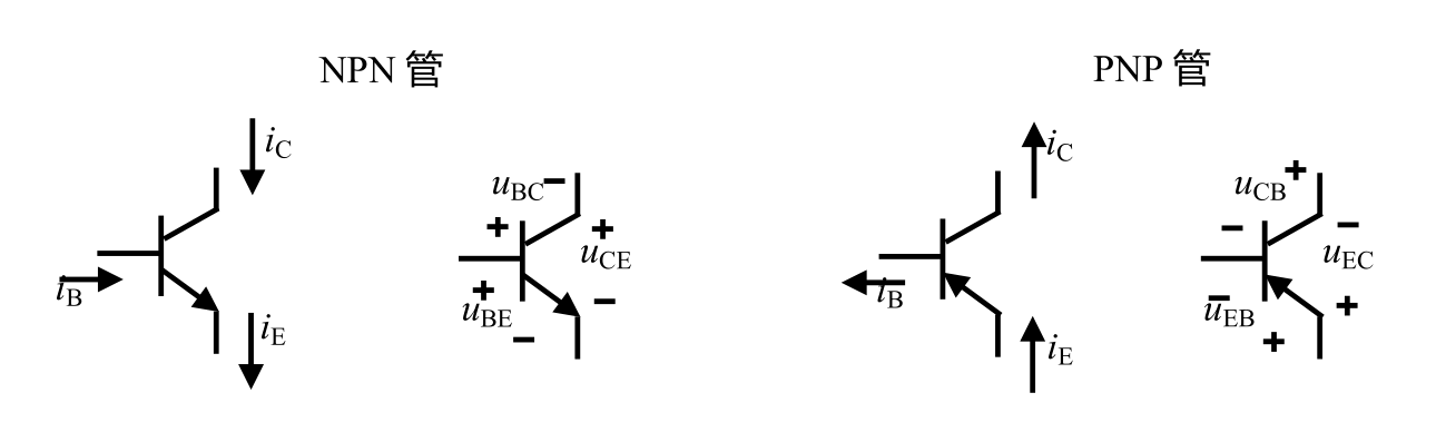
The direction of the transistor current depends on the direction of the emitter current.
- NPN: Current flows out of the emitter, so both the base and the collector have current flowing into them.
- PNP: Current flows into the emitter, so both the base and the collector have current flowing out of them.
Rules:
- Satisfies Kirchhoff's current law: \(i_B + i_C = i_E\)
- In the amplification state, the collector current is only controlled by the base current (\(i_C = \beta i_B\)), independent of the voltage between the collector and the emitter.
- When the base and the emitter are conducting, the voltage drop \(U_{BE}\) is approximately 0.7V.
Therefore, a transistor is a controlled current source, where a small current \(i_B\) controls a large current \(i_C\), depending on the transistor's constant amplification factor \(\beta\).
Thus, \(i_E=(1+\beta)i_B = \frac{1+\beta}{\beta}·i_C\)
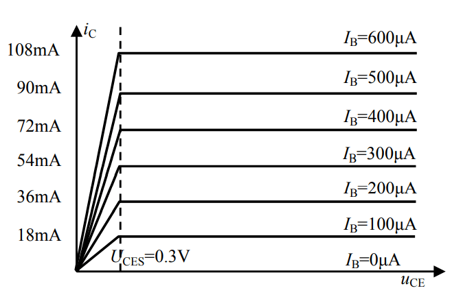
Output Voltage-Current Characteristics
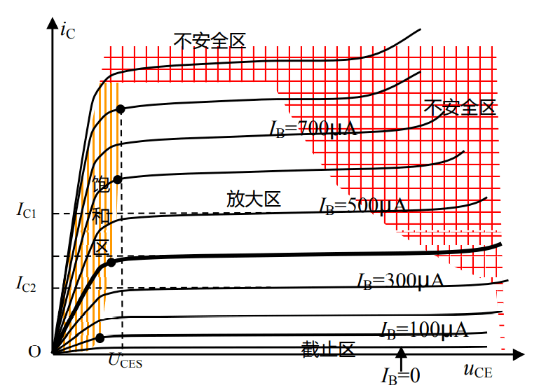
As shown in the graph, the output voltage-current characteristics of a transistor can be divided into the following regions:
- Amplification Region: In this region, the collector current \(i_C\) remains almost constant with respect to \(u_{CE}\), approximately satisfying \(i_C = \beta i_B\).
- Saturation Region: In this region, the collector current \(i_C\) increases as \(u_{CE}\) increases. It is generally considered that when \(u_{CE}\) is less than the saturation voltage drop \(U_{CES}\) (usually 0.3V), the transistor operates in the saturation region.
- Cutoff Region: This is the curve where \(I_B = 0\). However, at this point, \(i_C\) is not zero because there is a leakage current related to \(u_{CE}\). The cutoff region represents the state where the transistor has almost no current flowing in or out, approximating complete shutdown.
If we want to describe the voltage-current characteristics with mathematical formulas, we need to simplify the curve:
After simplification, we can understand it as follows:
- Amplification Region: Satisfies \(i_C = \beta i_B\), independent of \(u_{CE}\).
- Saturation Region: \(i_C\) increases linearly with \(u_{CE}\).
- \(U_{CES}\) Vertical Line: Separates the saturation region from the amplification region.
Capacitor-Coupled Amplifier Circuit
Transistor Operating States
-
Cut-off state
- Refers to the state where the base current does not generate significant current (\(I_{BQ}\) is very small, resulting in a very small \(I_{CQ}\)), and the collector and emitter are effectively open-circuited.
- \(I_{BQ} = 0, I_{CQ} = 0, I_{EQ} = I_{BQ}+I_{CQ}=0\). The emitter junction is unbiased/biased in reverse, and the collector junction is biased in reverse.
-
Amplification state
- Refers to the state where the transistor is at an appropriate \(I_{BQ}\) and satisfies \(I_{CQ} = \beta I_{BQ},I_{EQ} = (1+ \beta)I_{BQ}, I_{BQ} = \frac{V_{CC}-U_{BE}}{R_B}\)
- The emitter junction is biased in forward, and the collector junction is biased in reverse.
- This is the most commonly used state in analog electronics.
-
Saturation state
- \(I_{CQ} < \beta I_{BQ}\), but still varies with \(U_{CEQ}\). Both \(I_{BQ}\) and \(I_{CQ}\) are large, and \(I_{CQ}\) is no longer completely controlled by \(I_{BQ}\), and the voltage occupied by \(U_{CEQ}\) is very small.
- As long as \(U_{CEQ} < U_{CES}\), it enters the saturation state. At this time, increasing \(I_{BQ}\) will hardly increase \(I_{CQ}\).
- The emitter junction is biased in forward, and the collector junction is biased in forward.
- In analog electronics, it is advisable to avoid entering the saturation state, while in digital electronics, entering the saturation or cutoff state is expected.
- Inverted state
- The collector and emitter are reversed. Although it can still be used, it will cause a significant decrease in \(\beta\).
- The saturation state is like turning on the faucet, but there is no water in the tank, so only as much water as there is.
- The emitter junction is biased in reverse, and the collector junction is biased in forward.
There are three methods to determine the operating state of a transistor, namely estimation method, function solving method, and graphical method. The core of the estimation method is to assume that \(U_{BEQ}\) is approximately equal to 0.7 V, but with some error (the larger the voltage, the smaller the error); the function solving method requires knowledge of the mathematical expression of the input-output characteristics and solves the equation, which is generally not used; the graphical method uses the intersection of the volt-ampere characteristic curve and another straight line to determine the position of the static operating point, and then visually estimate the result.
Main Parameters of Transistors
- Current gain factor \(\beta\): Generally 10-100 times, but in practical applications, it is advisable to take 30-80 times (too small will result in insignificant amplification, too large will lead to unstable operation).
- Maximum collector current \(I_{CM}\): Exceeding this value may cause damage.
- Maximum collector power dissipation \(P_{CM}\)
- Collector-emitter breakdown voltage \(V_{CEO}\)
Determining the Operating State of a Transistor
Estimation Method
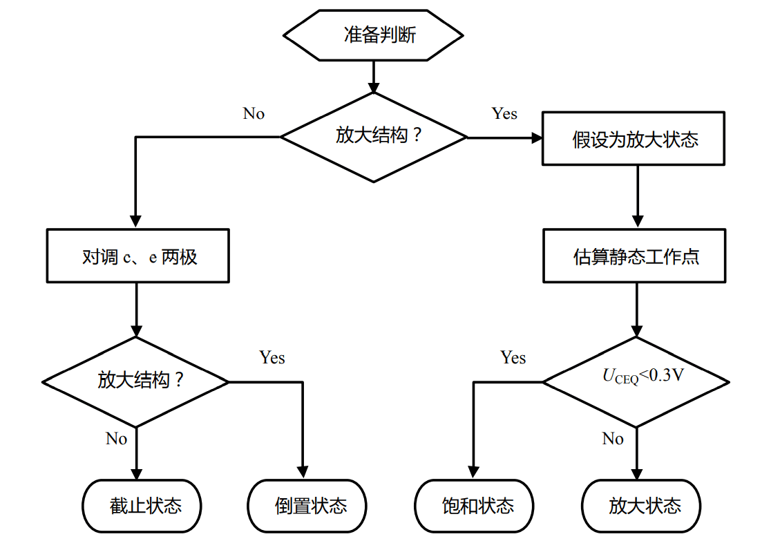
In the "Estimating Static Operating Point" part, a simple method is used to roughly estimate the static state of the transistor circuit (currents in each branch, voltages at each node), assuming that \(U_{BEQ}\) is approximately equal to 0.7 V (usually \(I_{CQ}\) and \(U_{CEQ}\) need to be calculated). The specific steps are as follows:
- Calculate \(I_{BQ}\) based on \(U_{BEQ} = 0.7 V\).
- Assume that the transistor is in the amplification state, i.e., \(I_{CQ} = \beta I_{BQ}\), and solve for \(U_{CEQ}\).
- If \(U_{CEQ} >= 0.3 V\) at this point, the assumption is valid, and the transistor is in the amplification state, with \(I_{CQ}\) and \(U_{CEQ}\) as the desired values.
- If \(U_{CEQ} < 0.3 V\), the assumption is not valid, and the transistor is in the saturation state.
Graphical Method
The core of the graphical method is to use the intersection of the volt-ampere characteristic curve and another straight line to determine the position of the static operating point, and then visually estimate the result.
Basic Amplifier Circuit
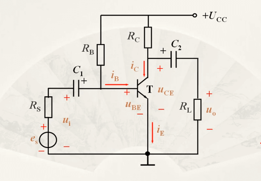
In the circuit shown above, the functions of each part are as follows:
- \(C_1\)/\(C_2\): Blocks DC and allows AC to pass through. Eliminates the influence of \(U_{CC}\). The values are usually in the range of a few microfarads to tens of microfarads.
- \(U_{CC}\): Provides the circuit function and provides an appropriate static operating point.
- \(R_B\): Provides an appropriate \(I_B\), with values typically ranging from tens of ohms to hundreds of kilohms.
- \(R_C\): Values are typically in the range of a few kilohms to tens of kilohms.
Analysis:
- Total base-emitter voltage \(U_{BE} = U_{BEQ}+u_i\)
- Total base current \(i_B=I_{BQ}+i_b\)
- Total collector current \(i_C=I_{CQ}+i_c\)
- Total collector-emitter voltage \(u_CE=V_{CC}-{i_C}{R_C}=V_{CC}-(I_{CQ}+i_c)R=U_{CEQ}+({-i_C}{R_C})\)
The shortcomings of this circuit are that although the structure is simple, the static operating point is unstable and greatly affected by various components.
Original: https://wiki-power.com/
This post is protected by CC BY-NC-SA 4.0 agreement, should be reproduced with attribution.This post is translated using ChatGPT, please feedback if any omissions.