Basic Components - Resistors
Selection of Resistors
Generally, the following four factors should be considered:
- Resistance Value: Determined according to the specific needs of the application circuit.
- Accuracy: Usually 1%. If used in current detection circuits (Rsense), lower resistance values and higher power ratings provide higher accuracy.
- Rated Power: Meets 50% derating. Different packages correspond to different power ratings, please refer to the table below.
- Size: Size is related to power rating and should be determined based on power and processing difficulty.
- Operating Temperature, Humidity, etc.: Factors to consider in specific situations.
- Temperature Coefficient: Must be considered if used in high-precision applications (sensor applications).
Parameters of Surface Mount Packages
| Imperial | Metric | Length (mm) | Width (mm) | Height (mm) | Rated Power (W) | Voltage Rating (V) |
|---|---|---|---|---|---|---|
| 0201 | 0603 | 0.60±0.05 | 0.30±0.05 | 0.23±0.05 | 1/20 | 25 |
| 0402 | 1005 | 1.00±0.10 | 0.50±0.10 | 0.30±0.10 | 1/16 | 50 |
| 0603 | 1608 | 1.60±0.15 | 0.80±0.15 | 0.40±0.10 | 1/10 | 50 |
| 0805 | 2012 | 2.00±0.20 | 1.25±0.15 | 0.50±0.10 | 1/8 | 150 |
| 1206 | 3216 | 3.20±0.20 | 1.60±0.15 | 0.55±0.10 | 1/4 | 200 |
| 1210 | 3225 | 3.20±0.20 | 2.50±0.20 | 0.55±0.10 | 1/3 | 200 |
| 1812 | 4832 | 4.50±0.20 | 3.20±0.20 | 0.55±0.10 | 1/2 | 200 |
| 2010 | 5025 | 5.00±0.20 | 2.50±0.20 | 0.55±0.10 | 3/4 | 200 |
| 2512 | 6432 | 6.40±0.20 | 3.20±0.20 | 0.55±0.10 | 1 | 200 |
Resistance Values of Resistors
Marking Methods
- Three-digit Marking: \(XXY = XX * 10^Y\)
- For example, a resistor marked as 272 has an actual resistance value of \(27 * 10^2=27 * 100=2.7k\).
- Four-digit Marking: \(XXXY = XXX * 10^Y\)
- Letter Marking for Decimal Point Position:
Rrepresents the decimal point.- For example, a resistor marked as 5R6 has an actual resistance value of 5.6 Ω.
M,k,mcan also represent the decimal point, corresponding toMΩ,kΩ,mΩ, respectively.
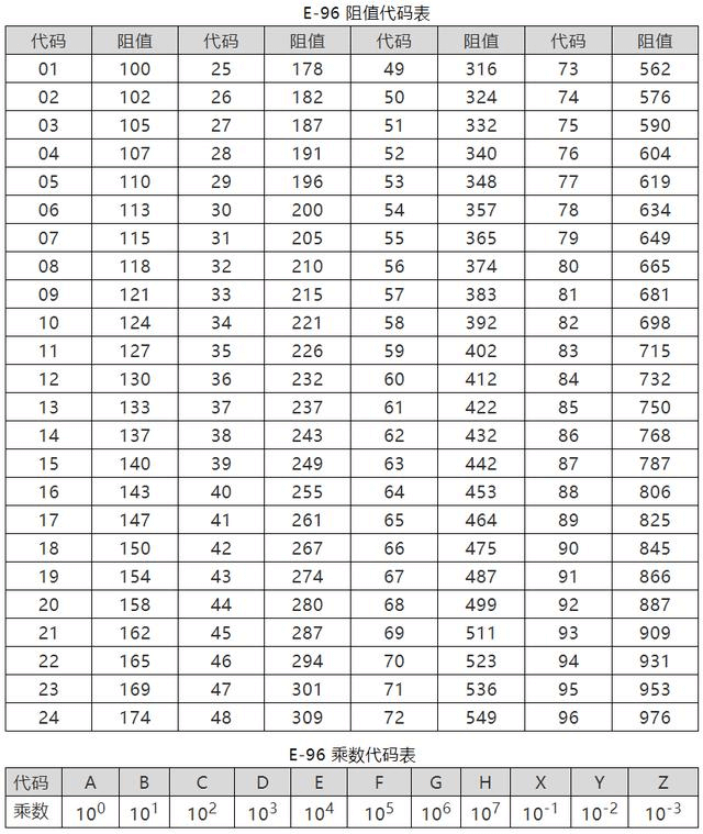
- Three-digit Multiplier Code Marking: In
XXY,XXrepresents the code for the significant digits, andYindicates the power of 10. Please refer to the standard resistor value table below.- For example, a resistor marked as 01C has an actual resistance value of \(100*10^2=10 kΩ\).
Standard Resistor Values
According to the commonly used priority number specification, the E96 series is generally used more frequently, and its resistance values and multiplier code table are as follows:
Failure Modes of Resistors
Ranked by the probability of occurrence, they are:
- Open Circuit: Defect or degradation of resistor film; may occur when subjected to excessive instantaneous power shock.
- Resistance Drift Beyond Specifications: May occur after aging.
- Pin Breakage: Welding process defects, solder contamination; may occur when the pins of plug-in resistors are repeatedly bent.
- Burnout: Working at a power rating above the rated power for a long time may cause burnout and open circuit.
- Welding Issues: Cold solder joints and other issues.
- Wire Breakage/Open Circuit: May occur under mechanical stress or instantaneous power shock.
Use of 0 Ohm Resistors
- Used as a jumper to cross over areas where no traces are laid.
- Used as a shorting socket.
- Single-point connection between digital ground and analog ground (sometimes using inductors or ferrite beads).
- Reserved resistance for debugging purposes.
Overcurrent capability of 0-ohm resistors in different packages (generally used with a 50% reduction in rated current):
| Package | Rated Current (Maximum Current) /A |
|---|---|
| 0201 | 0.5 (1) |
| 0402 | 1 (2) |
| 0603 | 2 (3) |
| 0805 and up | 2 (5) |
Applications of Resistors
Voltage Divider Circuit
Resistors are connected in series for voltage division, with the following circuit characteristics:
- The current through each resistor is the same, i.e., the current in each resistor is equal, i.e., \(I = I_1 = I_2 = I_3\).
- The total voltage is equal to the sum of the voltage drops across each resistor, i.e., \(V = V_1 + V_2 + V_3\).
- The total resistance is equal to the sum of the resistances, i.e., \(R = R_1 + R_2 + R_3\).
For example, the feedback pin of a voltage regulator is generally connected to a voltage divider circuit consisting of two resistors, which provides an output voltage close to the internal reference voltage.
Current Divider Circuit
Resistors are connected in parallel for current division, with the following circuit characteristics:
- The voltage across each branch is equal.
- The total current is equal to the sum of the branch currents, i.e., \(I = I_1 + I_2 + I_3\).
- The reciprocal of the total resistance is equal to the sum of the reciprocals of the branch resistances, i.e., \(\frac{1}{R} = \frac{1}{R_1} + \frac{1}{R_2} + \frac{1}{R_3}\).
In practical circuit design, current dividers are often used to protect resistors connected in parallel to the collector and emitter of a transistor. In cases where the power of a linear power regulator is insufficient, resistors can also be used between the input and output terminals to increase the output current.
Current Limiting Circuit
Generally used for current limiting of LEDs. Resistors are connected in series with the circuit containing the LED to determine the resistance value based on the forward voltage drop of the LED (generally 0.7 V) and the rated current of the LED. It should be noted that the calculated actual operating current should be less than the rated operating current of the LED.
Current limiting circuits can also be used in hot-swappable circuits.
Impedance Matching Circuit
The purpose of impedance matching is to maximize the power obtained by the load, i.e., the load resistance is equal to the source resistance. The derivation process is as follows:
Assuming the load resistance is R, the electromotive force of the power source is U, and the internal resistance is r, the current through R is:
It can be seen that the smaller R is, the larger the current. The voltage across R is:
The larger R is, the larger the output voltage \(U_R\) is. The power of R is:
Since r is constant, when R=r, \(\frac{(R-r)^2}{R}=0\), and the maximum power \(P_{max}=\frac{U^2}{4r}\) can be obtained.
RC Charging and Discharging Circuit
\(\tau=RC\) (if the units of R and C are Ω and F, the unit of the result is s).
The RC circuit can be regarded as a delay circuit or a filtering circuit, which smoothes the rising and falling edges of the pulse signal, and can achieve different rise times by adjusting the values of R and C.
Pull-up and Pull-down Circuit
Pull-up is used to clamp an uncertain signal to a high level (while also acting as a current limiter); pull-down is the opposite.
Generally, resistors below 50 Ω are strong pull-up/pull-down, and resistors above 100 kΩ are weak pull-up/pull-down.
Other Circuits
- Operational amplifier peripheral circuit.
- Anti-interference circuit to improve surge voltage capability.
- Load circuit (to prevent circuit from being unloaded).
References and Acknowledgements
- "Hardware: A Hundred Thousand Whys - Passive Components"
- SMD Resistor Package, Dimensions, and Power Correspondence Table
- Power Master Class Series (2) | Things You Don't Know About Resistors and Capacitors
Original: https://wiki-power.com/ This post is protected by CC BY-NC-SA 4.0 agreement, should be reproduced with attribution.
This post is translated using ChatGPT, please feedback if any omissions.