Basic Components - Operational Amplifier
As the saying goes, the operational amplifier is the ultimate goal of analog electronics. An operational amplifier is a device that can amplify electrical signals (voltage/current/power). Not only that, it can also be used as a buffer, filter, and perform various mathematical operations (integration, differentiation, multiplication, logarithm), etc.
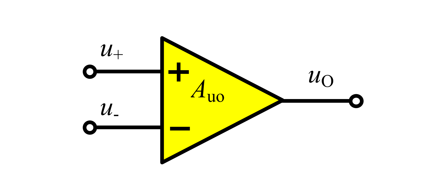
The operational amplifier has a pair of differential input terminals (in-phase input voltage \(u_+\) and out-of-phase input voltage \(u_-\)), a single-ended output terminal \(u_o\), and a pair of power supply pins \(V_+\) and \(V_-\) (usually not shown). It takes in the in-phase input voltage \(u_+\) and out-of-phase input voltage \(u_-\), performs internal comparison operations, and amplifies the output through the output terminal \(u_o\). The output impedance of the output terminal \(u_o\) is 0, and the outgoing current is provided by the positive power supply terminal \(V_+\), while the incoming current is provided by the negative power supply terminal \(V_-\).
When the operational amplifier is operating in the linear region, it satisfies the relationship:
where \(A_{uo}\) is the open-loop voltage gain of the operational amplifier (u represents voltage, o represents open), which is generally infinite.
Operational Amplifier Operating Modes
The voltage transfer characteristics of an integrated operational amplifier are shown in the following figure:
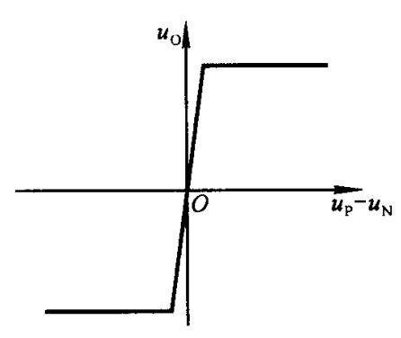
The figure is divided into the linear region and the nonlinear region:
- Operating in the linear amplification region: the slope of the diagonal line represents the open-loop voltage gain.
- Operating in the nonlinear region: also known as saturation state, represented by the horizontal lines at the two ends of the figure, the output voltage is \(-U_{om}\) (the voltage of the negative power supply terminal \(V_-\)) or \(+U_{om}\) (equivalent to the voltage of the positive power supply terminal \(V_+\)).
Operational Amplifier Power Supply
The power supply for the operational amplifier is generally divided into single power supply or dual power supply. In a single power supply configuration, \(V_+\) is connected to a positive voltage and \(V_-\) is connected to ground. In a dual power supply configuration, \(V_+\) is generally connected to a positive voltage and \(V_-\) is connected to a negative voltage. Different power supply configurations result in different frequency performance and input/output ranges.
In addition, the operational amplifier can operate in an asymmetric positive/negative power supply (\(V_+\)/\(V_-\)) configuration (e.g., \(V_+\) is 5V and \(V_-\) is -3V). It does not need to be referenced to ground and can still function properly.
Rail-to-rail operation of an operational amplifier refers to the ability of the output voltage to reach the power supply voltage. For example, if it is a non-rail-to-rail operational amplifier, and the power supply is 0-5V, the output voltage may only reach 0.7-4.3V, while a rail-to-rail output can reach 0-5V.
Virtual Short and Virtual Open
Virtual Short
Virtual short is viewed from the perspective of voltage. Under the condition of negative feedback, the voltages at the positive and negative input terminals are approximately equal, resembling a short circuit (but not a real short circuit), which is called a virtual short.
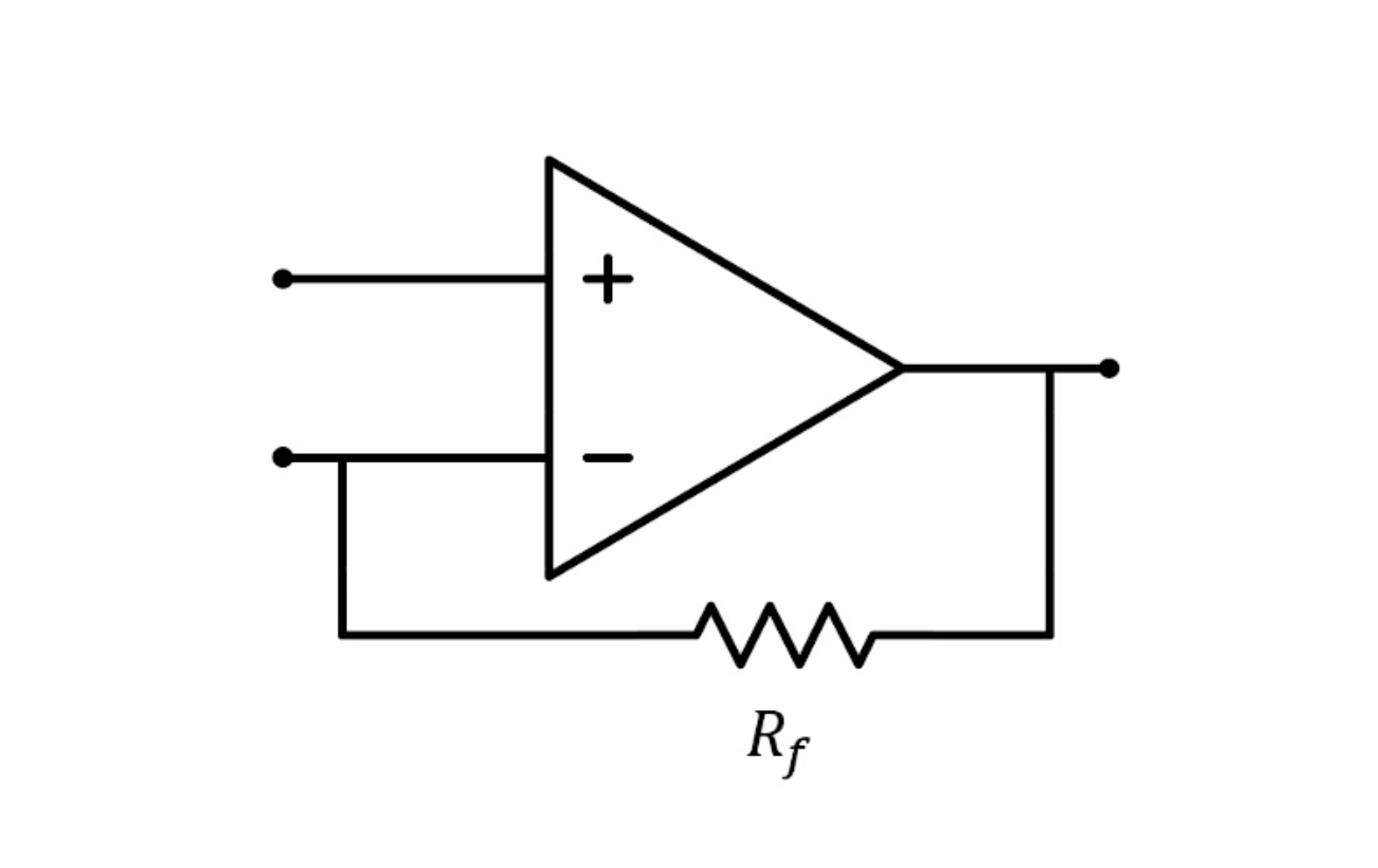
Referring to the circuit with negative feedback, it can be seen that if the voltage at the in-phase input terminal is slightly higher than the voltage at the out-of-phase input terminal, the negative feedback circuit will increase the voltage at the out-of-phase input terminal until it is equal to the voltage at the in-phase input terminal. Conversely, if the voltage at the in-phase input terminal is slightly lower than the voltage at the out-of-phase input terminal, the voltage at the out-of-phase input terminal will also follow the voltage at the in-phase input terminal.
Virtual Open
Virtual open is viewed from the perspective of current. The input impedance of the operational amplifier's two input terminals is very high, and the incoming current is in the microampere range, approximating zero current flow, which is called a virtual open.
Note: The high input impedance of the operational amplifier's two input terminals is true for general cases. There are also exceptions, such as current feedback amplifiers.
Common Operational Amplifier Circuits
Due to the infinite open-loop voltage gain of the operational amplifier, special circuit structures are needed to achieve the desired amplification effect.
Voltage Follower
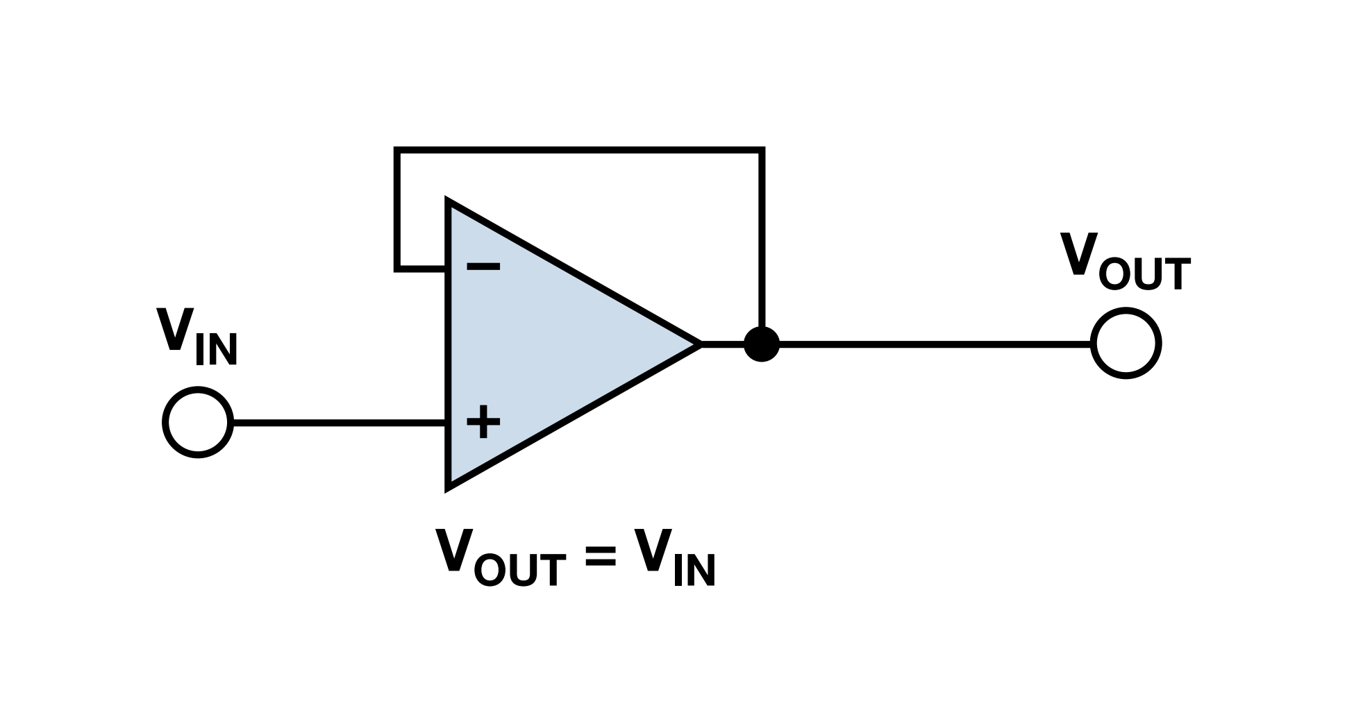
The voltage follower (also known as a buffer) is used to buffer high-impedance signal sources and low-impedance loads.
Inverting Amplifier
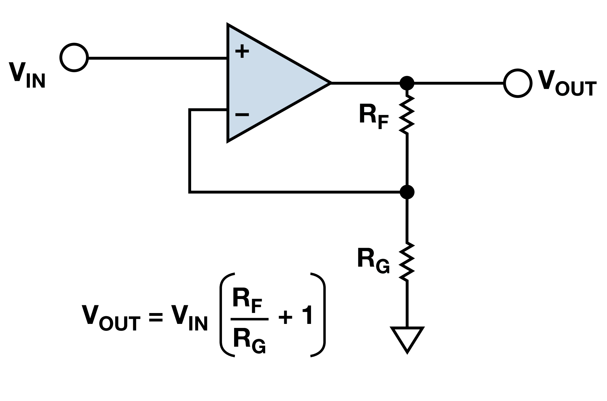
The inverting amplifier amplifies the input signal in phase with the input.
Effect: By adjusting the resistance values of \(R_G\) and \(R_F\), the relationship between \(V_{OUT}\) and \(V_{IN}\) can be proportionally amplified.
Principle:
Translate into English:
- Because of virtual short, \(V_- = V_{IN}\)
- Because of virtual open, the input current at the \(V_-\) terminal can be ignored, so \(I_{R_G}=I_{R_F}\). According to Ohm's law, \(\frac{0–V_-}{R_G}=\frac{V_- - V_{OUT}}{R_F}\), and we get \(V_{OUT}=V_{IN}(\frac{R_F}{R_G}+1)\).
Inverting Amplifier
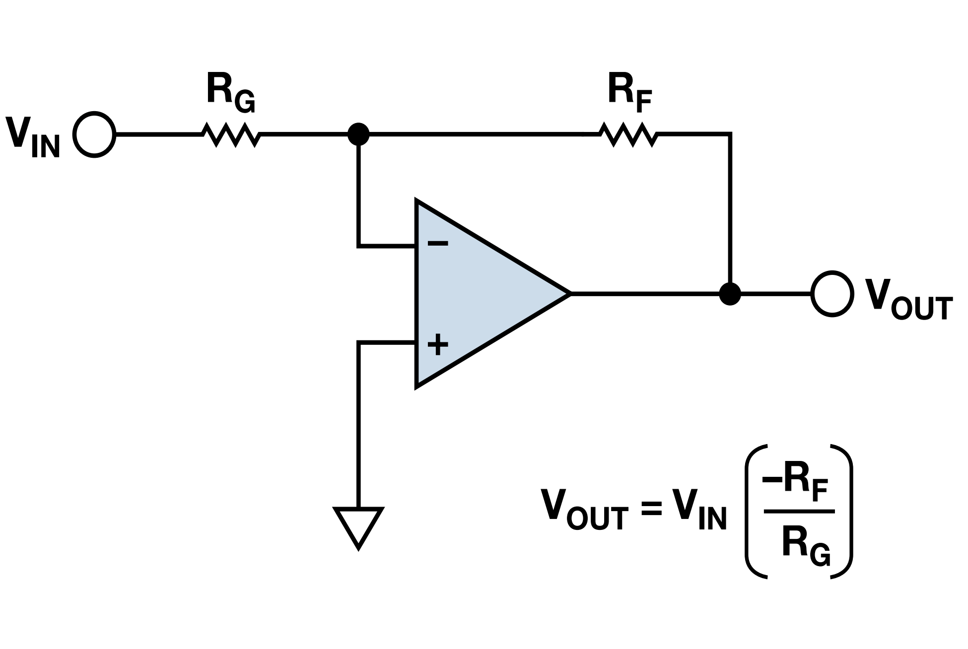
The output of the inverting amplifier is inverted with respect to the input, which amplifies the signal and outputs it in reverse.
Voltage Subtractor / Differential Amplifier
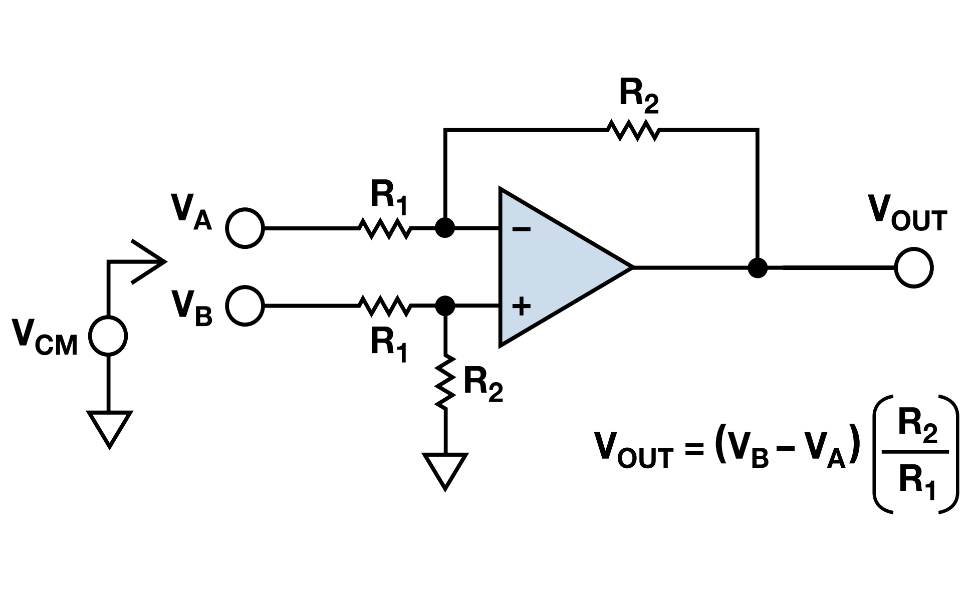
The voltage subtractor / differential amplifier amplifies the difference between two voltages and suppresses the common-mode voltage.
Voltage Adder
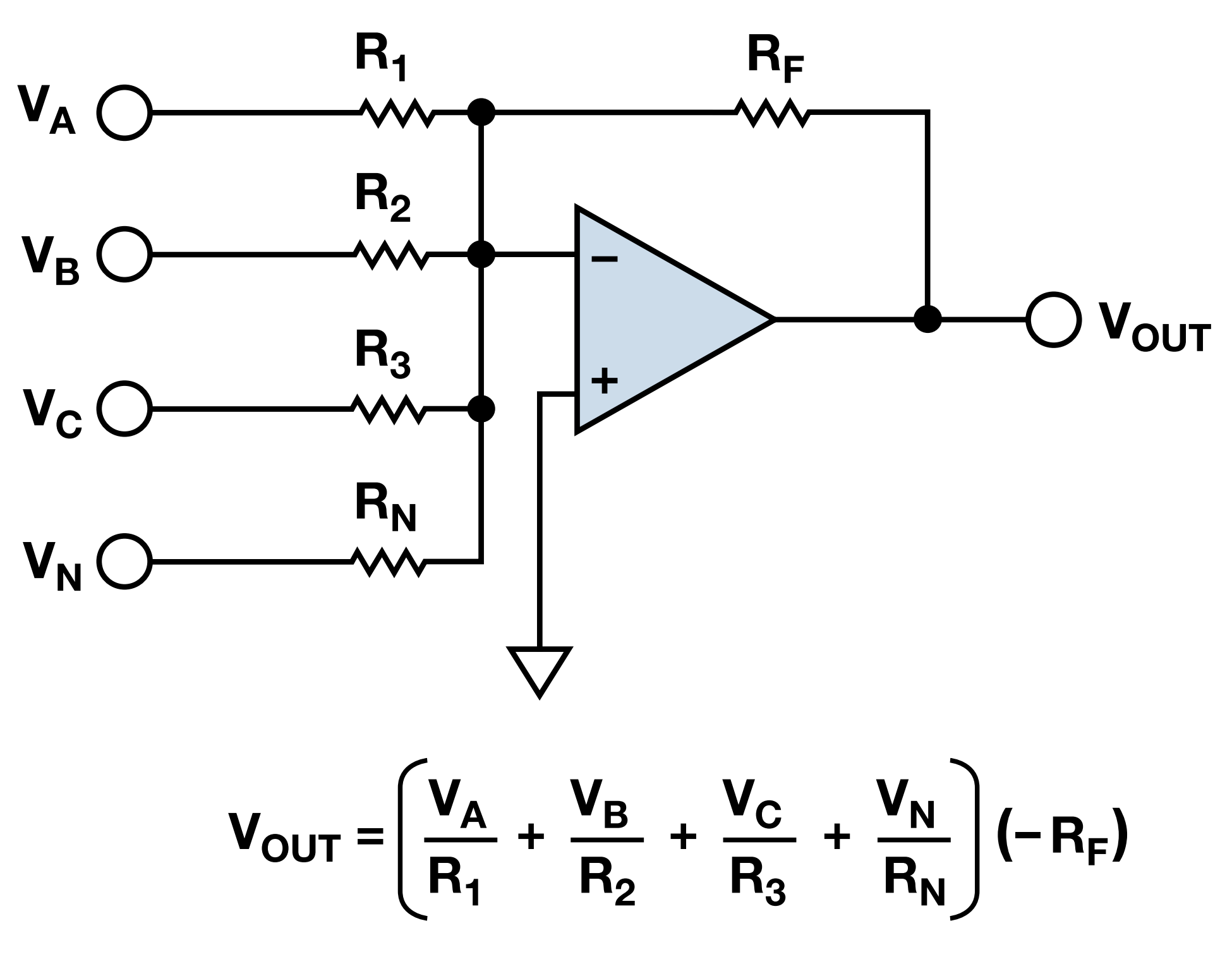
The voltage adder is used to sum multiple voltages.
Low-Pass Filter / Integrator
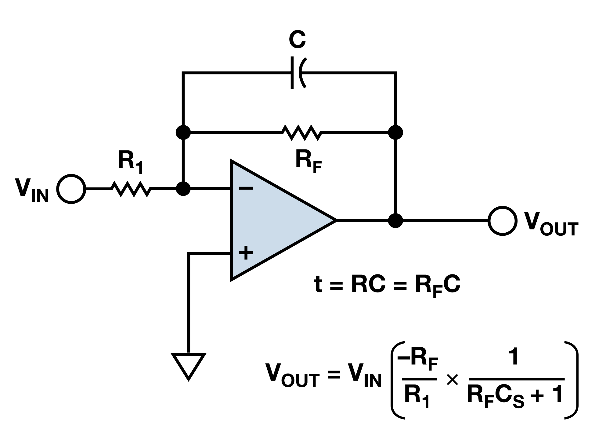
The low-pass filter / integrator is used for low-pass filtering of signals, limiting the signal bandwidth.
High-Pass Filter / Differentiator
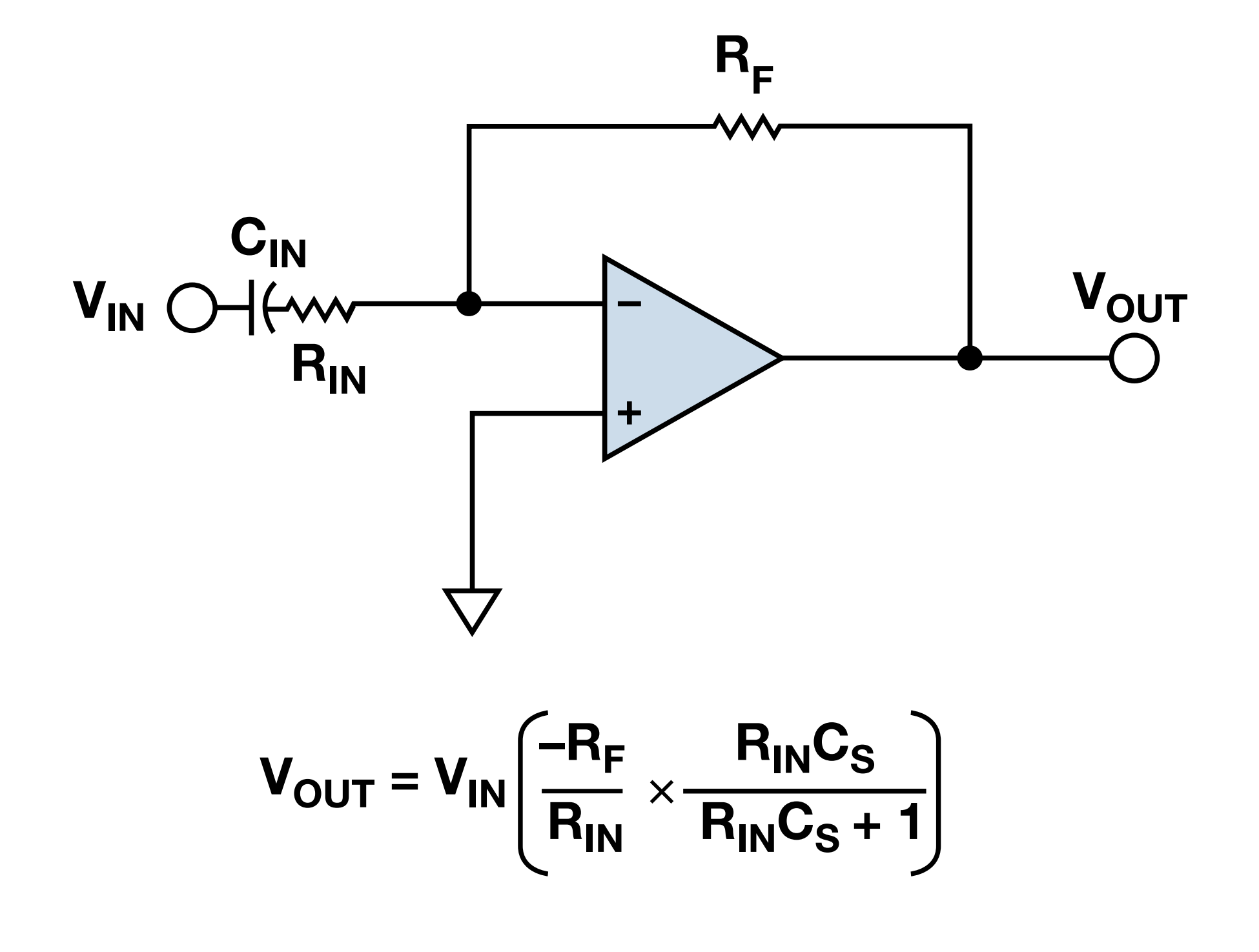
The high-pass filter / differentiator is used to isolate DC signals and amplify AC signals.
Differential Amplifier
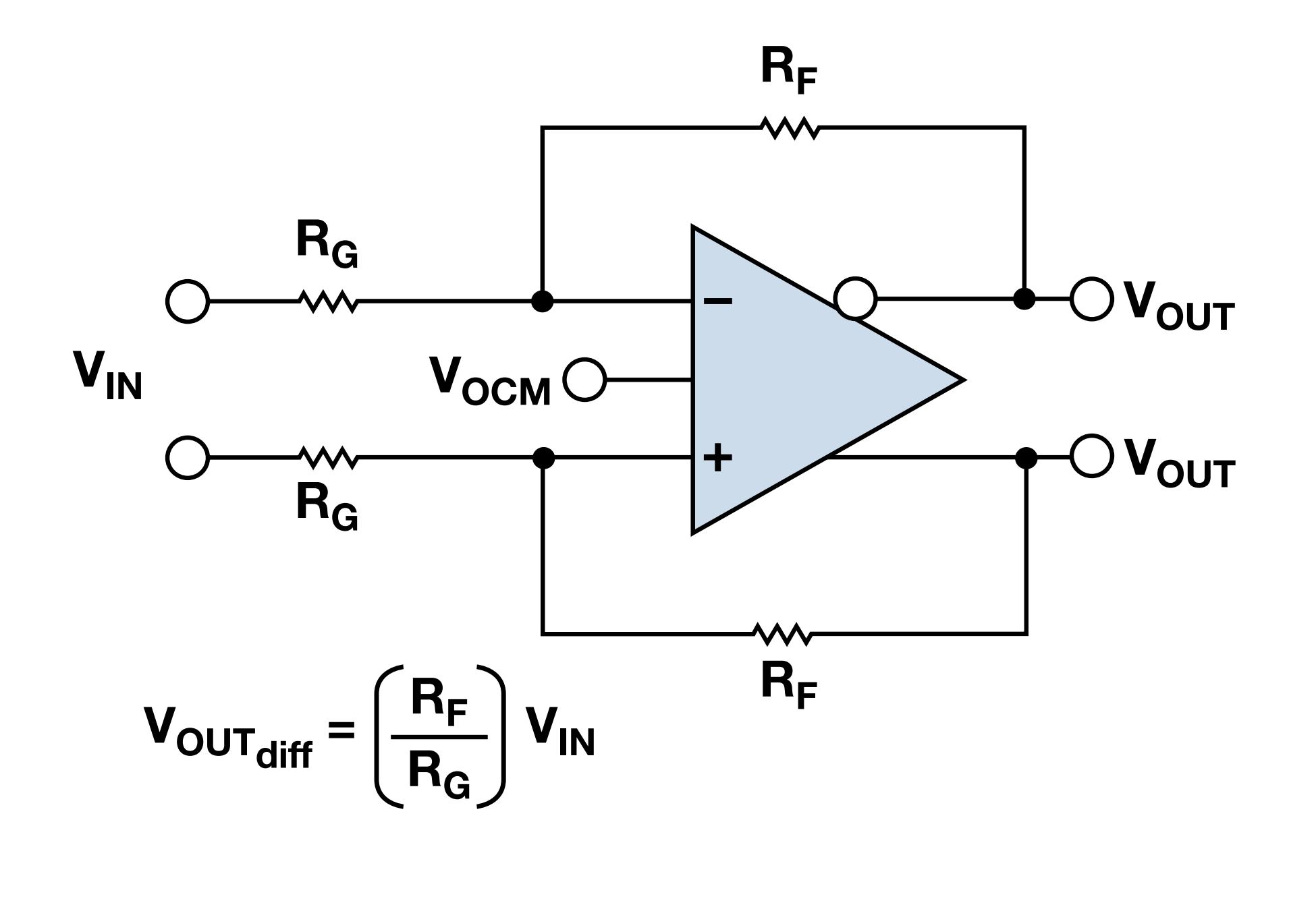
The differential amplifier is used to drive differential input ADCs from differential or single-ended signal sources.
Instrumentation Amplifier
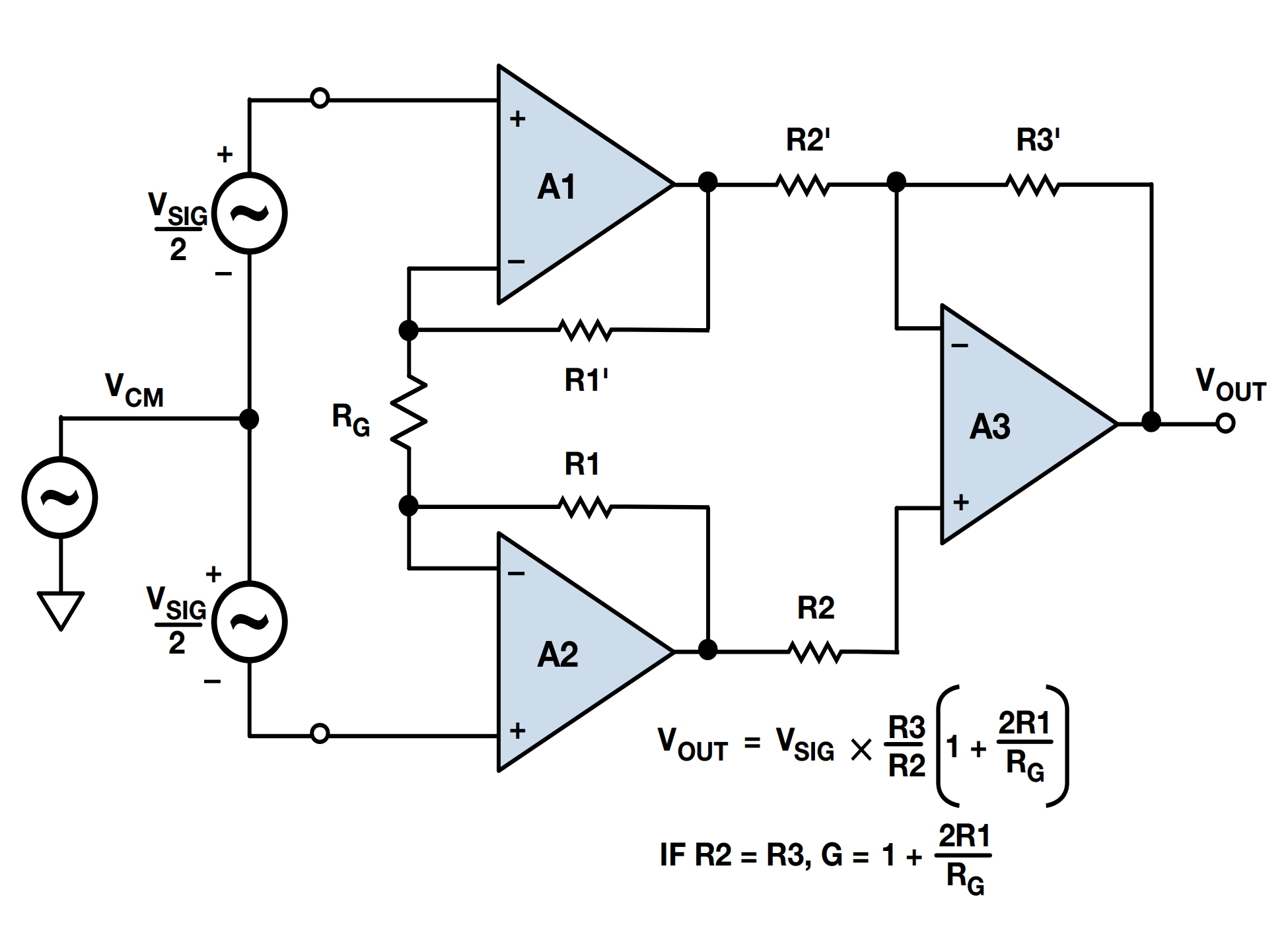
The instrumentation amplifier is used to amplify low-level differential signals and suppress common-mode signals. Here, \(V_{IN}\) is the voltage difference between the two input terminals.
Parameters of Operational Amplifiers
Open-Loop Voltage Gain
The open-loop voltage gain \(A_{uo}\) represents the amplification factor of the operational amplifier in the linear amplification region, expressed in dB.
Offset Voltage
Offset voltage \(V_{OS}\) (Input Offset Voltage), sometimes referred to as input bias voltage, refers to the condition where the input of the operational amplifier is 0V. In this condition, the ideal output of the operational amplifier should be zero. However, the actual output of the operational amplifier is not zero. The ratio of the actual output voltage to the gain is called the offset voltage. The offset voltage actually reflects the symmetry inside the operational amplifier.
The factors affecting the offset voltage include temperature (corresponding to the temperature drift of the offset voltage) and power supply fluctuations (corresponding to the power supply rejection ratio). The offset voltage is a DC bias that adds up on the output. If the output is an AC signal, only consider whether the superimposed signal will exceed the supply voltage and cause signal distortion.
We know that the amplification formula for the inverting amplifier is \(V_{OUT}=V_{IN}(\frac{R_F}{R_G}+1)\). If we consider the influence of the offset voltage, then the output becomes \(V_{OUT}=(V_{IN}+V_{OS})(\frac{R_F}{R_G}+1)\).
Offset Voltage Temperature Drift
The offset voltage temperature drift \(T_C V_{OS}\) represents the ratio of the change in input offset voltage to the change in temperature (within the operating temperature range of the chip).
The offset voltage temperature drift can cause changes in the offset voltage, affecting the operational amplifier output.
Input Offset Current
The input offset current \(I_{OS}\) refers to the difference between the DC current flowing into or out of the two input terminals of the operational amplifier when the output is zero. The input offset current is influenced by the manufacturing process.
Input Bias Current
The bias current \(I_B\) refers to the average of the DC current flowing into or out of the two input terminals of the operational amplifier when the output is zero.
The bias current is influenced by the manufacturing process. For bipolar process, the input bias current is between 10nA and 1μA; for field-effect transistor process, the input bias current is generally less than 1nA.
The error can be eliminated by adding matching resistors at the inverting terminal.
Gain-Bandwidth Product
Translate into English:
The Gain-Bandwidth Product (GBW) refers to the product of the open-loop voltage gain and the measurement frequency (bandwidth) at a certain frequency (usually the -3dB gain attenuation of the operational amplifier).
The Gain-Bandwidth Product is influenced by the frequency response characteristics of the internal capacitance of the operational amplifier. If it is found that the gain of the high-frequency signal is limited in the design, an operational amplifier with a larger GBP parameter must be selected.
Common Mode Rejection Ratio
The Common Mode Rejection Ratio (CMRR) refers to the ratio of the common mode voltage range (CMVR) to the variation of the input offset voltage (ΔV{O) within this range, expressed in dB.}
The Common Mode Rejection Ratio is influenced by the circuit symmetry (such as offset current and other parameters) and the linear operating range. This parameter is used to indicate the ability of the differential amplifier circuit to suppress common mode signals and amplify differential mode signals. A higher CMRR means that the interference signals of the common mode input can be more effectively suppressed, improving the signal-to-noise ratio.
Slew Rate
The Slew Rate (SR), also known as the rate of change, represents the maximum rate of change of the output voltage under large signal conditions.
Where f is the maximum frequency (usually the bandwidth) and V_{pk} is the maximum peak-to-peak value of the amplified output signal.
The Slew Rate is used to evaluate the operational amplifier's ability to adapt to the speed of signal changes. It is a parameter that measures the operational amplifier's working speed when subjected to large amplitude signal effects. The output voltage changes linearly only when the absolute value of the slope of the input signal change is less than SR.
Other Parameters
- Common Mode Voltage Range (CMVR): Also known as the input voltage range. If the input voltages at both input terminals exceed this range, the output will experience clipping or excessive nonlinearity.
- Full Power Bandwidth: Refers to the maximum frequency measured under unit gain, at which a sinusoidal signal can be obtained with the rated output voltage without signal distortion caused by the slew rate.
- Operating Power Supply Voltage Range: The range of power supply voltages that can be applied when the operational amplifier is operating normally.
- Power Supply Rejection Ratio (PSRR): The ratio of the change in power supply voltage to the change in input offset voltage, expressed in dB.
- Settling Time: The time required for the amplifier to settle to a predetermined accuracy level or a certain percentage of the output voltage after applying a step input.
- Power Supply Current: The current required by the power supply when the amplifier is operating under no load.
Selecting an Operational Amplifier Based on Parameters
The following steps can be taken to select an operational amplifier based on parameters:
- Determine the type of input signal: For DC signals, pay attention to offset current and offset voltage; for differential inputs, consider choosing an instrumentation amplifier; for high-frequency AC signals, pay attention to the Gain-Bandwidth Product (GBW) and Slew Rate (SR).
- Determine the required accuracy: Consider the impact of offset voltage, bias current, offset current, and Common Mode Rejection Ratio (CMRR) on accuracy, and decide whether to use a high-impedance or precision operational amplifier.
- Consider environmental conditions: Pay attention to the temperature range of the operational amplifier, temperature drift, and the impact of Power Supply Rejection Ratio (PSRR).
- Consider other requirements: Number of channels, single/dual power supply (rail-to-rail signal distortion is small, full-scale output is possible), power rating (for high voltage or high current situations).
Selecting an Operational Amplifier Based on Application
Based on application, operational amplifiers can be roughly categorized as follows:
- General-purpose operational amplifiers: Devices that do not have high requirements for various parameters, with a focus on versatility and cost-effectiveness.
- Audio operational amplifiers: Ultra-low noise (high fidelity) and low power consumption (long battery life).
- High-speed operational amplifiers (GBW ≥ 50 MHz): Low power consumption and low noise SNR.
- Power operational amplifiers: High voltage and high current.
- Precision operational amplifiers (V_{os} < 1mV): Low offset voltage, or low temperature drift, low noise, low power consumption, wide bandwidth.
References and Acknowledgements
- I got it! The working principle of the operational amplifier is explained well!
- Three classic operational amplifier circuits
- Operational amplifier selection guide
- Operational amplifier selection quick reference guide
- TI operational amplifier selection guide
- Detailed explanation and analysis of operational parameters [TI FAE Sharing]
Original: https://wiki-power.com/
This post is protected by CC BY-NC-SA 4.0 agreement, should be reproduced with attribution.This post is translated using ChatGPT, please feedback if any omissions.