RF - Components and Systems - Resistors
Resistors are properties of conductive materials. In an AC environment, resistors sometimes still exhibit their DC properties (for example, in the bias network of a transistor), which may disrupt the RF operating point of a circuit.
Equivalent Circuit of Resistors
In RF circuits, the equivalent model of a resistor is as follows:
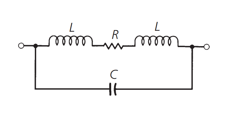
In the diagram, R represents the resistor itself, L represents the equivalent inductance of the leads, and C is a combination of parasitic capacitance (which varies depending on the structure of the resistor). Generally, carbon film resistors have poor high-frequency performance because they are composed of dense dielectric or carbon particles, with a small parasitic capacitance between each pair of carbon particles. These parasitic effects are important components of the equivalent circuit.
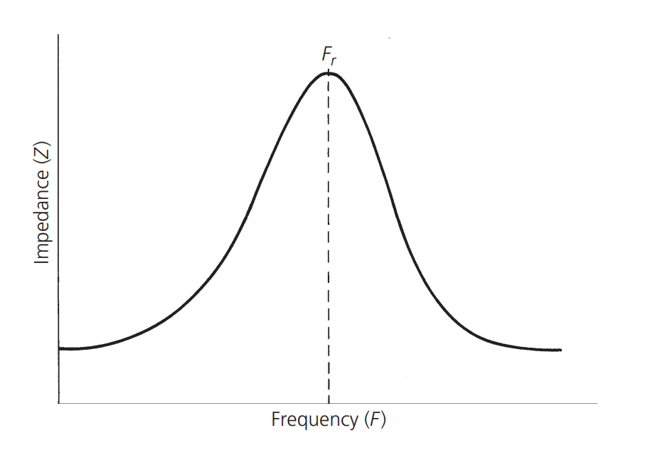
Wirewound resistors also pose problems in RF circuits, often exhibiting varying impedance at high frequencies, especially for low resistance values within the 10MHz-200MHz frequency range. The parasitic inductance of wirewound resistors is larger than that of carbon film resistors, and the inductance value can be approximately calculated using the formula for single-layer air-core inductors (mentioned later in this text). Due to the distinct characteristics of inductance in wirewound resistors, their impedance increases with frequency. At a certain frequency (\(F_r\)), the inductance (\(L\)) will resonate with the parallel capacitance (\(C\)), resulting in a peak impedance. After the peak, as the frequency increases, the impedance decreases, as shown in the following graph:
Metal film resistors exhibit the best characteristics within the frequency range. Although their equivalent circuit is the same as carbon film and wirewound resistors, the values of the parasitic elements in the equivalent circuit are reduced.
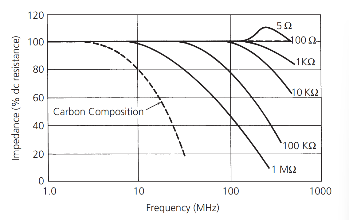
As shown in the graph, the impedance of metal film resistors starts to decrease at approximately 10MHz, due to the parallel capacitance in the equivalent circuit. However, at very high frequencies or very low resistance values (50Ω), the impedance is affected by the lead inductance and skin effect. The lead inductance creates a resonant peak, while the skin effect affects the slope of the curve.
References and Acknowledgements
- "RF Circuit Design (Second Edition)" by Chris Bowick
Original: https://wiki-power.com/ This post is protected by CC BY-NC-SA 4.0 agreement, should be reproduced with attribution.
This post is translated using ChatGPT, please feedback if any omissions.