Basic Knowledge of Digital Circuits
Number Systems and Code Systems
Number System: Rules for representing quantities. The composition of each digit and the carry rules from the least significant digit to the most significant digit, such as decimal system. Code System: Rules for representing things, the rules followed when encoding.
Analog Circuit: Represents information with continuous analog voltage/current values. Digital Circuit: Represents information with a discrete sequence of voltages.
Commonly used number systems: 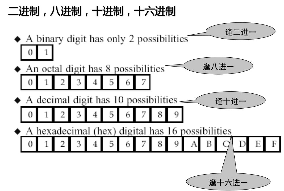
Conversion of any number in any base to decimal:
\((526)_8=5*8^2+2*8^1+6*8^0=(342)_{10}\)
\((2A.7F)_H=2*16^1+10*16^0+7*16^{-1}+15*16^{-2}=(42.4960937)_D\)
\(D=\sum K_iN^i\)
Two's Complement of Binary Numbers
- The highest bit is the sign bit (0 for positive, 1 for negative).
- The two's complement of a positive number is the same as its original representation.
- The two's complement of a negative number = One's complement of the absolute value + 1
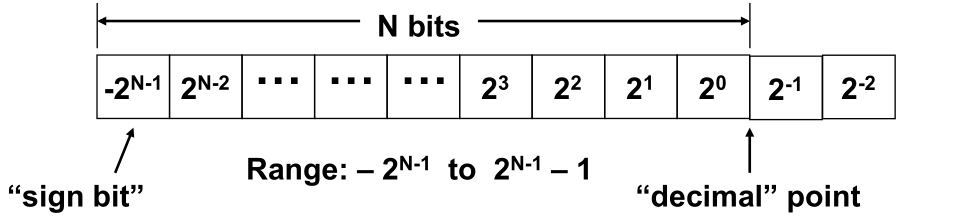
+5 = (0 0101)
-5 = (1 1011)1101.0110
= –2 3 + 2 2 + 2 0 + 2 -2 + 2 -3
= – 8 + 4 + 1 + 0.25 + 0.125
= – 2.625
Code Systems
Fixed-length codes:
- 4-bit BCD code
- ASCII
- Gray code: The encoding sequence changes in order, when changing according to the order in the table, only one bit of adjacent codes changes state
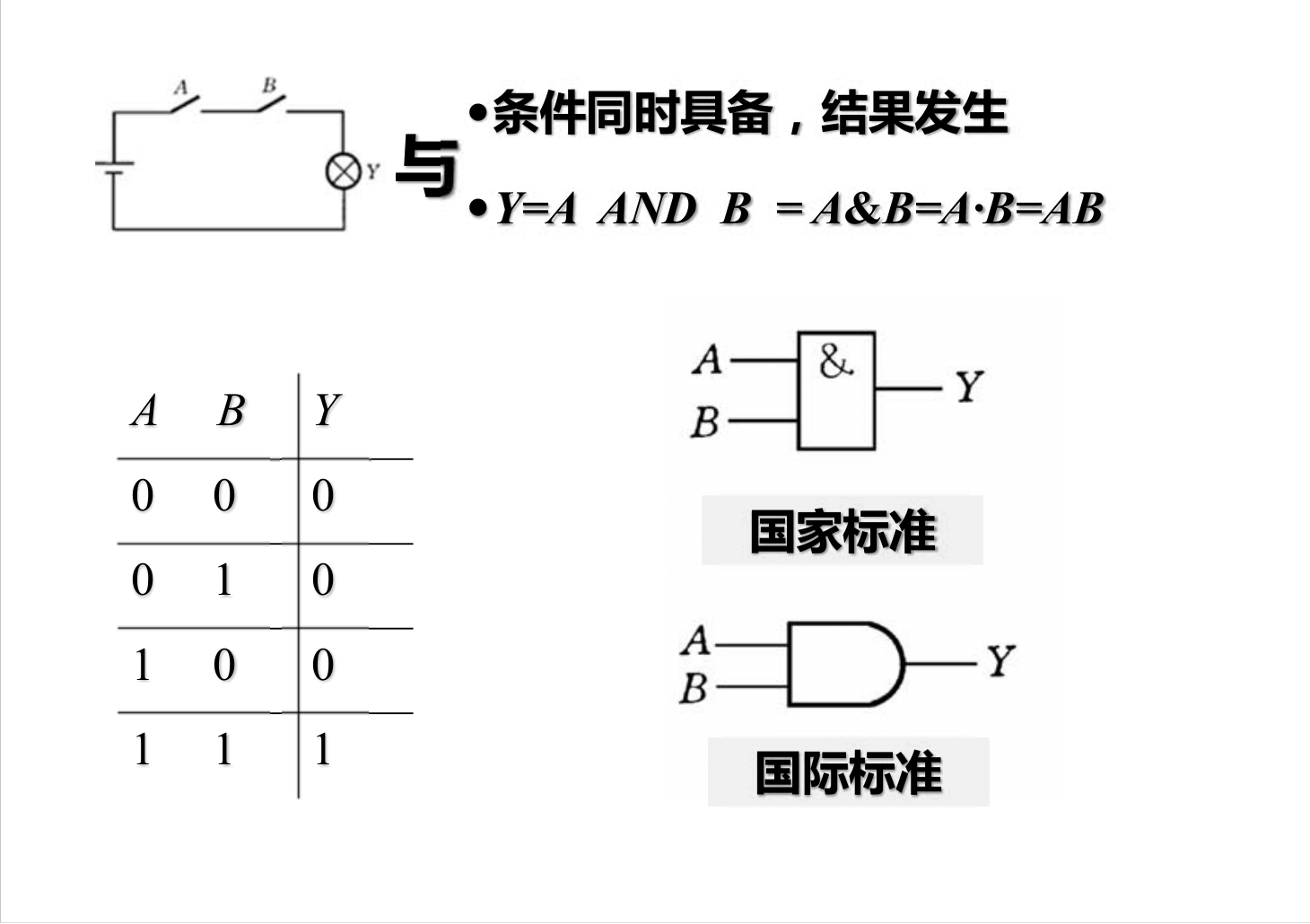
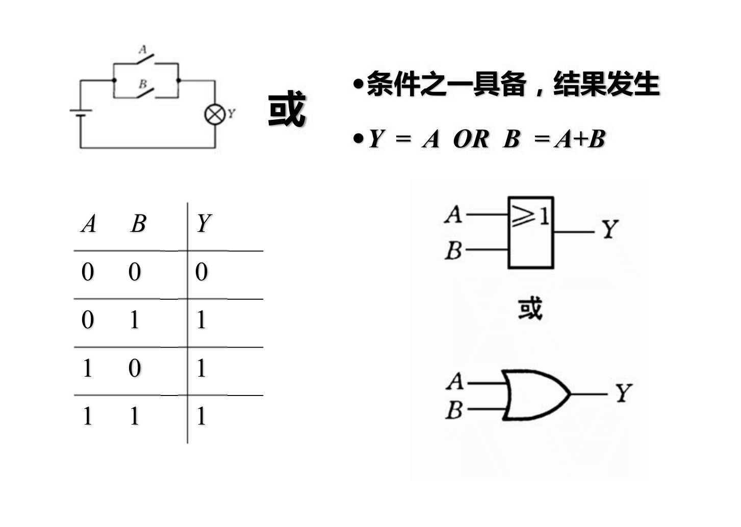
Fundamentals of Logic Algebra
XOR: 1 if inputs are different, 0 if inputs are the same
\(Y=A'B+AB'\) 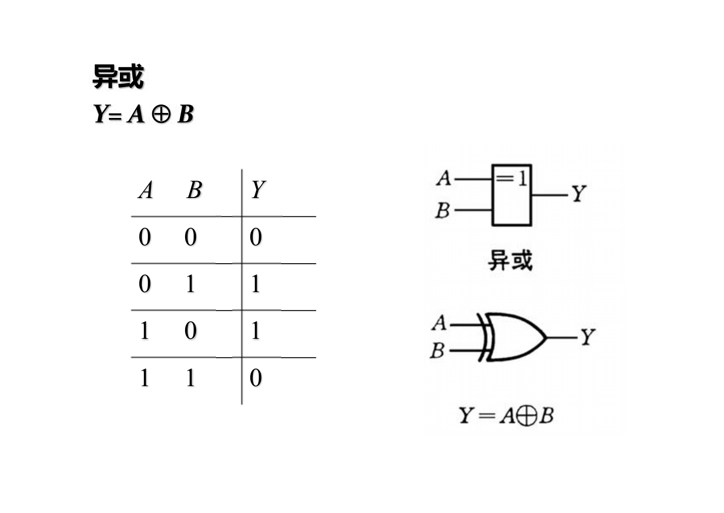
XNOR: 1 if inputs are the same, 0 if inputs are different \(Y=AB+A'B'\) 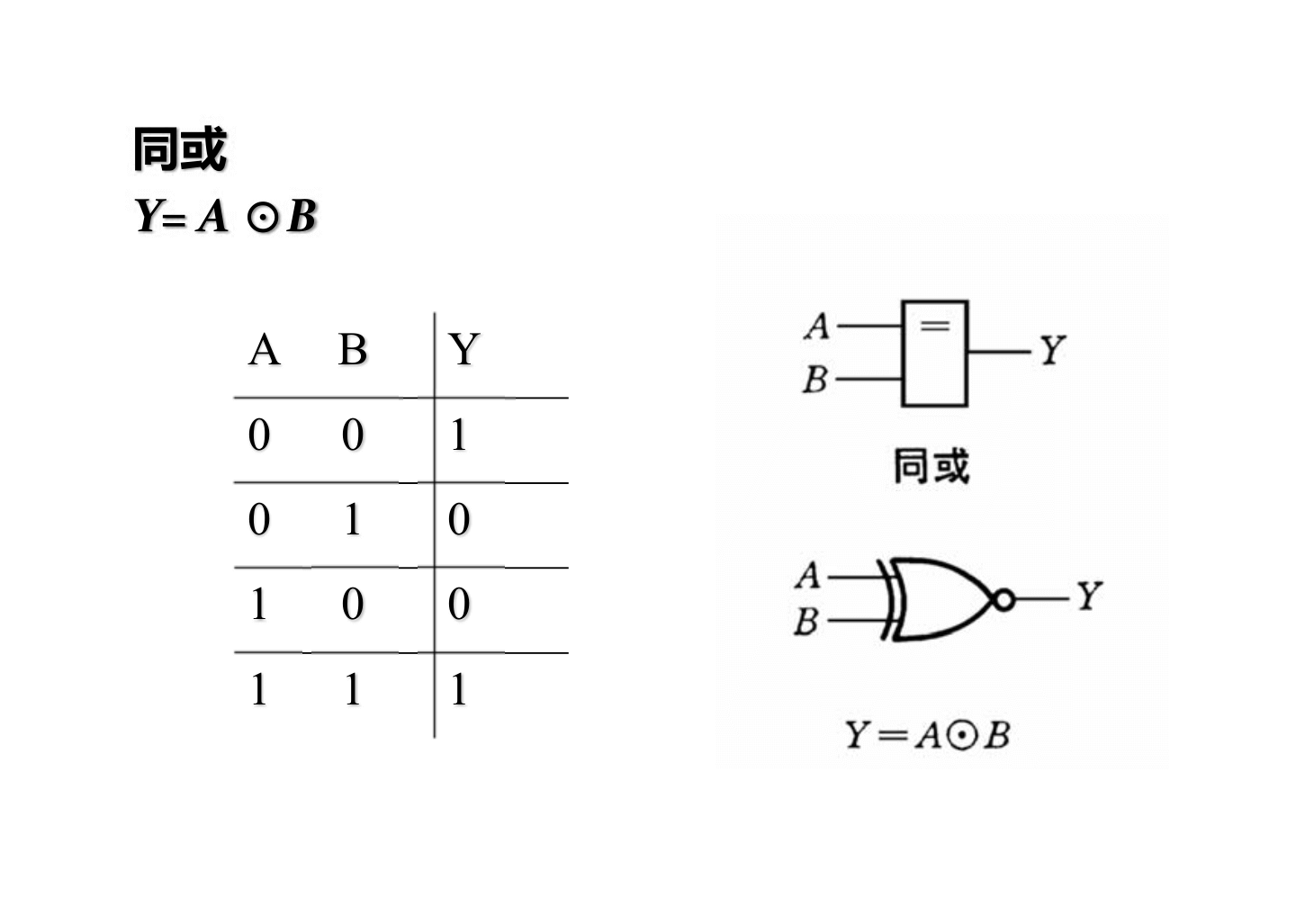
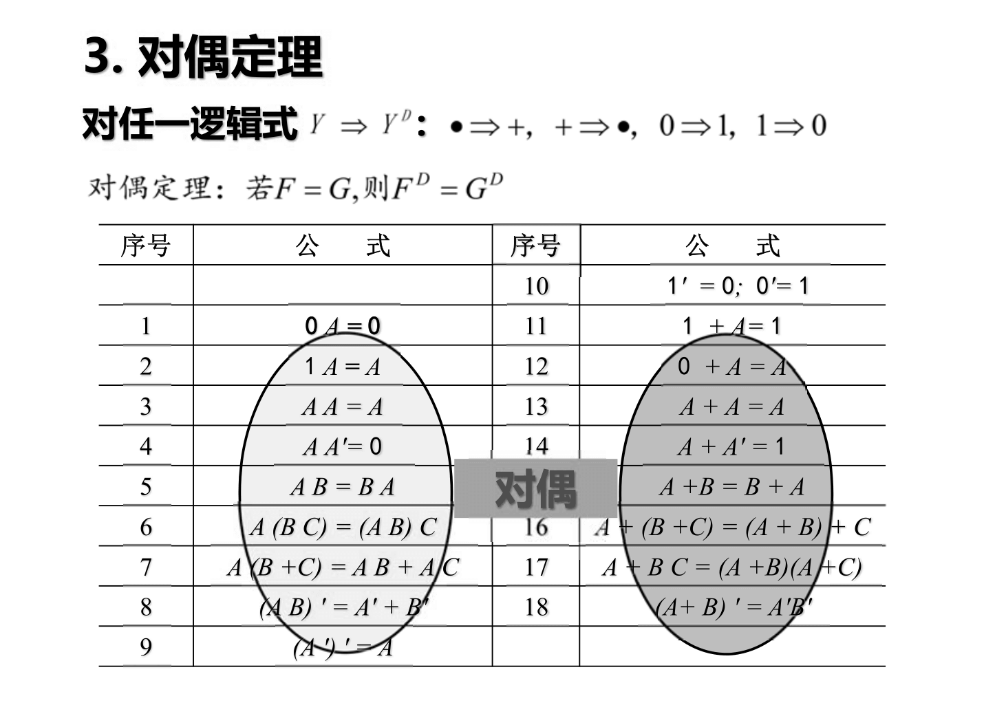
Basic Logic Operation Formulas
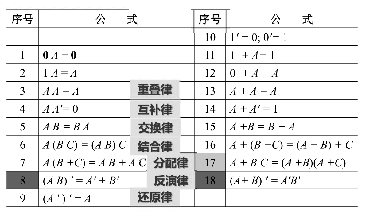
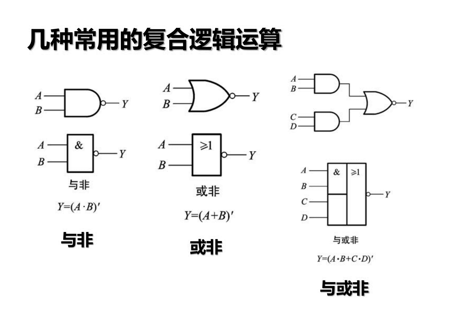
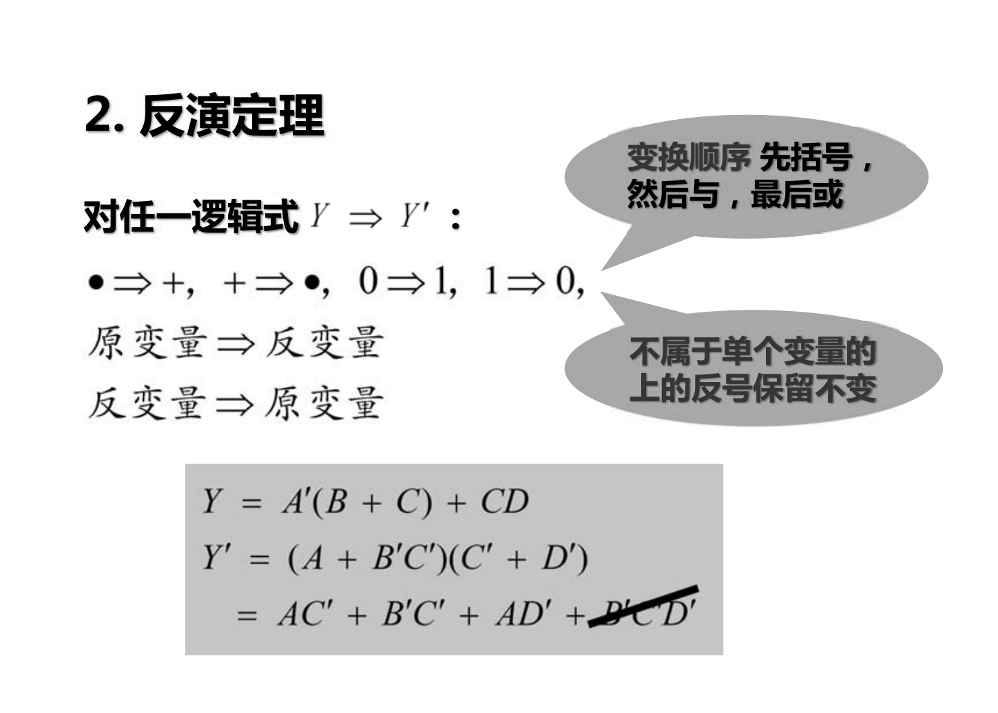
\((A B) ' = A' + B'\)
\((A+ B)' = A'B'\)
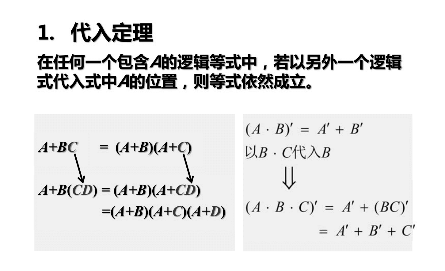
\(A + B C = (A +B)(A +C)\)
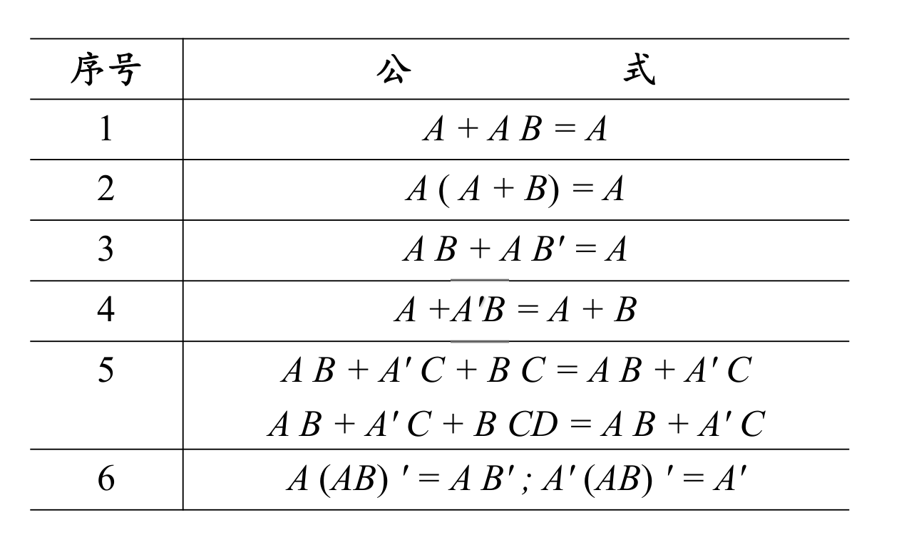
Common Logic Operation Formulas
Basic Theorems of Logic Algebra
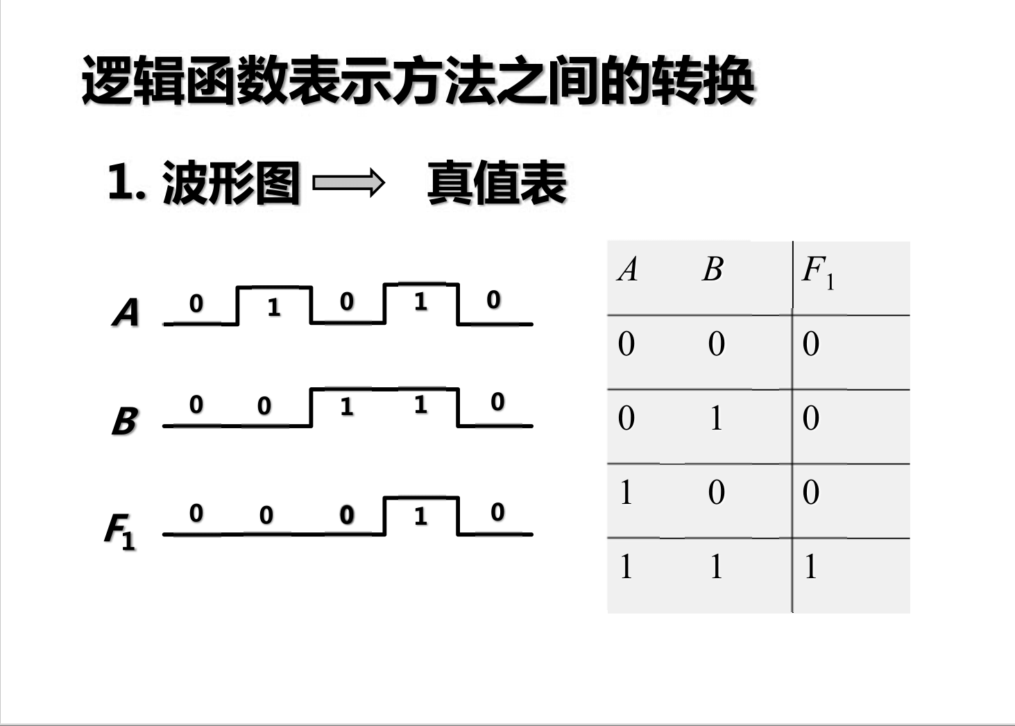
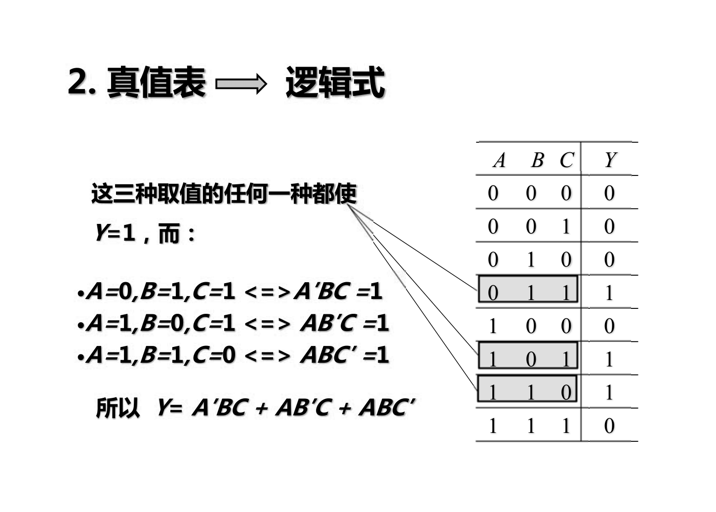
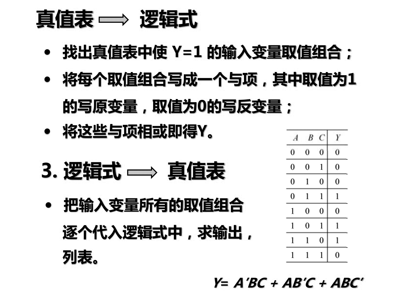
Representation Methods of Logic Functions
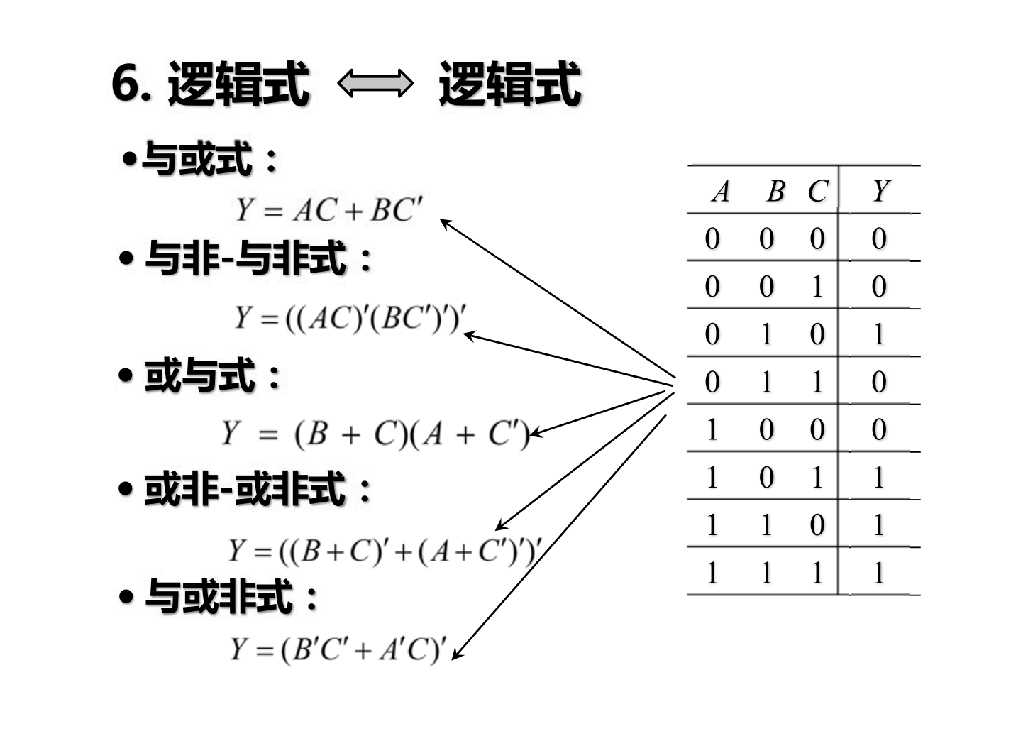
- Truth table
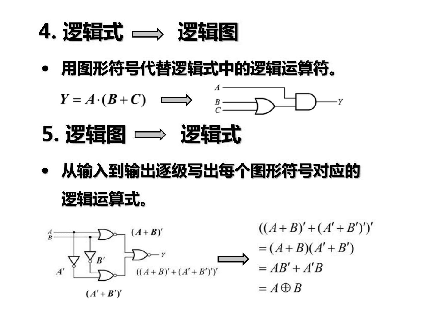
- Logic expression
- Logic diagram
- Waveform diagram
Simplification of Logical Functions
The simplest form of logical expressions
Minterms
It represents the number of rows in the truth table
Representing all possible and unique situations
Simplification by Formulas
Repeatedly applying basic formulas and common formulas to eliminate redundant AND terms and redundant factors. 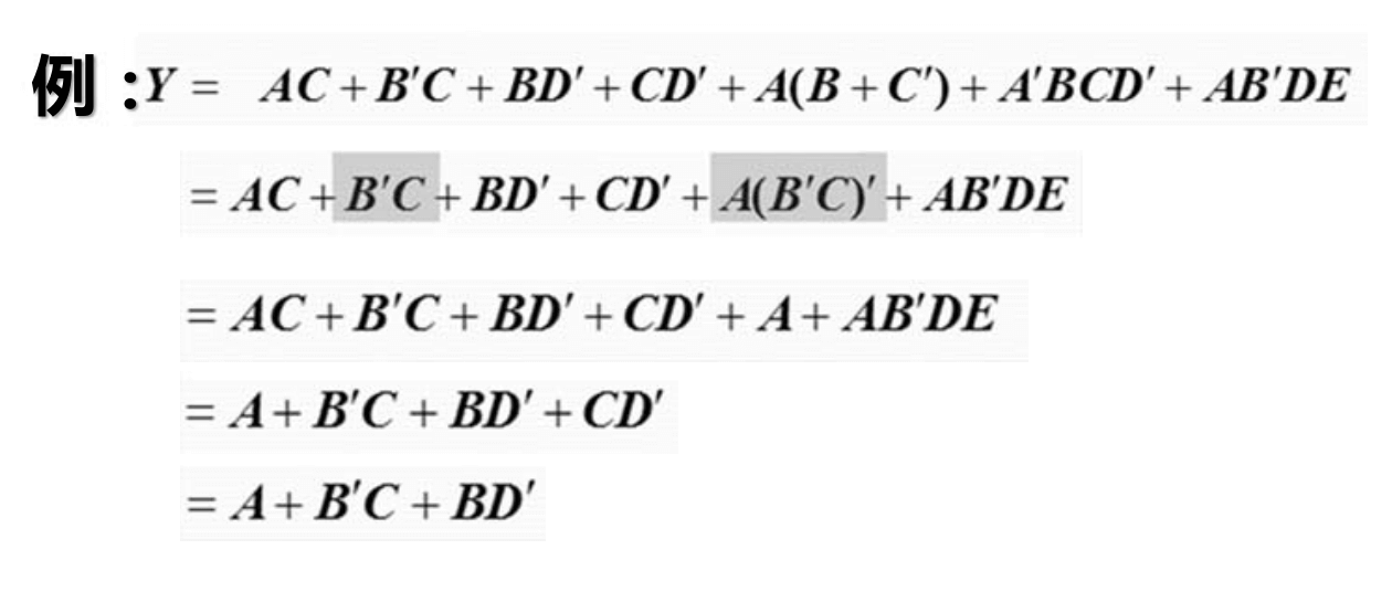
Simplification by Karnaugh Map
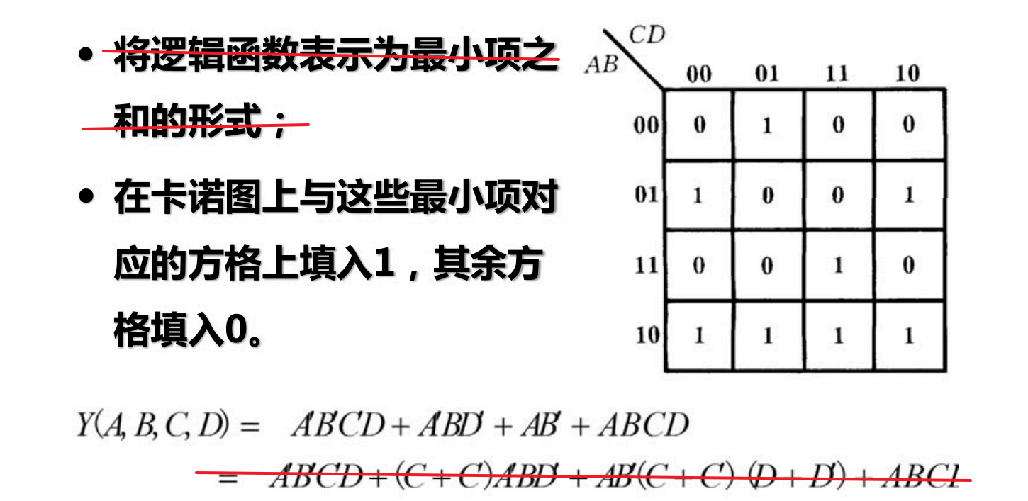
It is not necessary to fully convert to minterms.
If minterms are repeated, fill in 1.
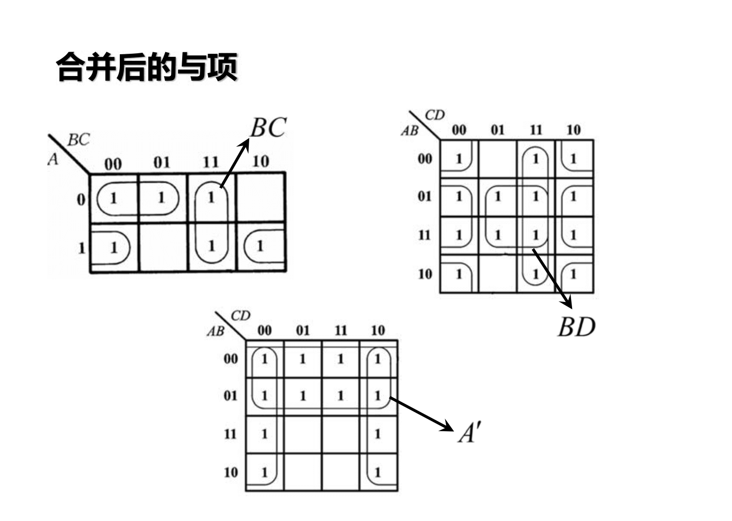
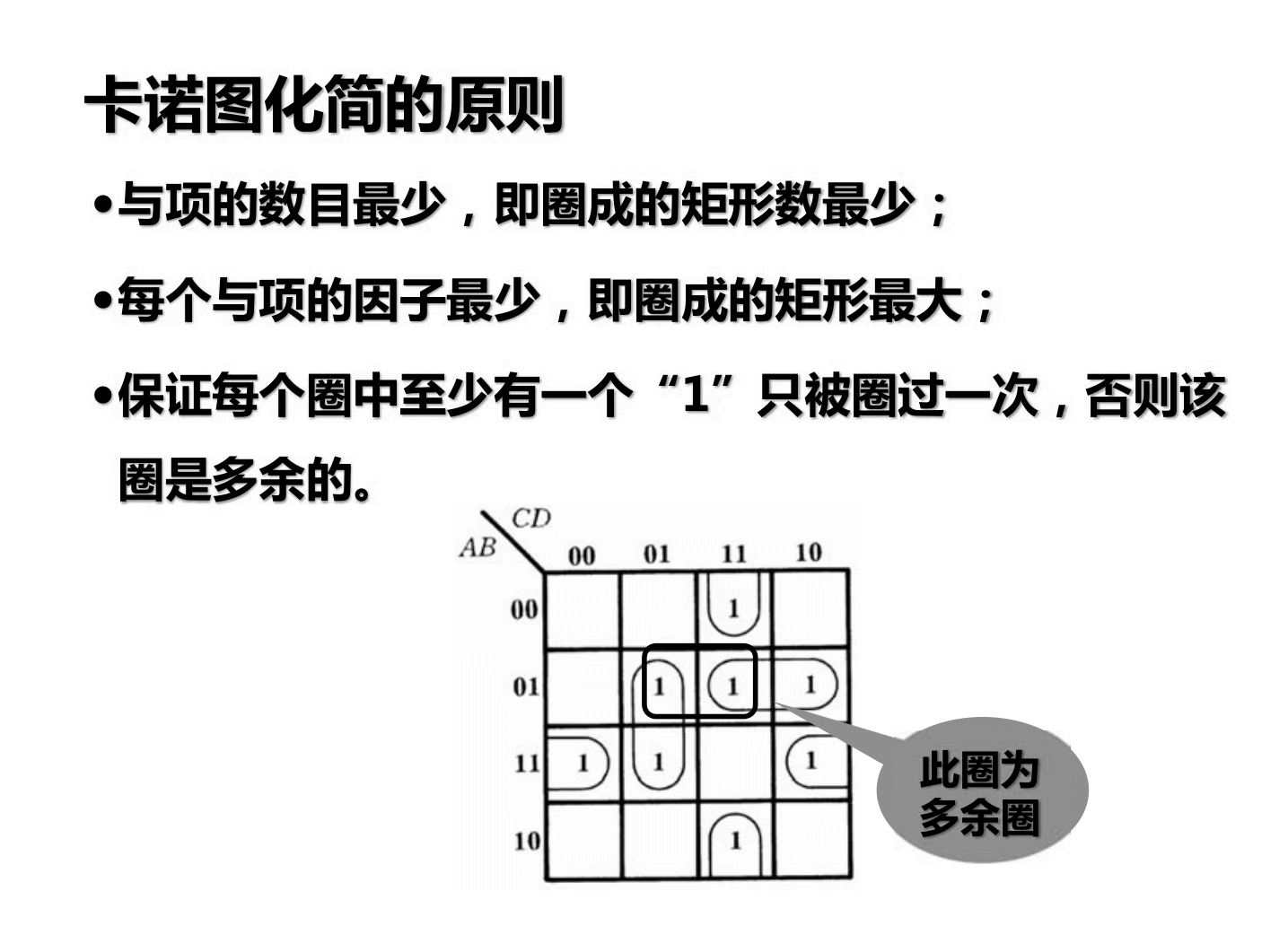
If there are fewer 0s, you can also encircle the 0s and take the complement.
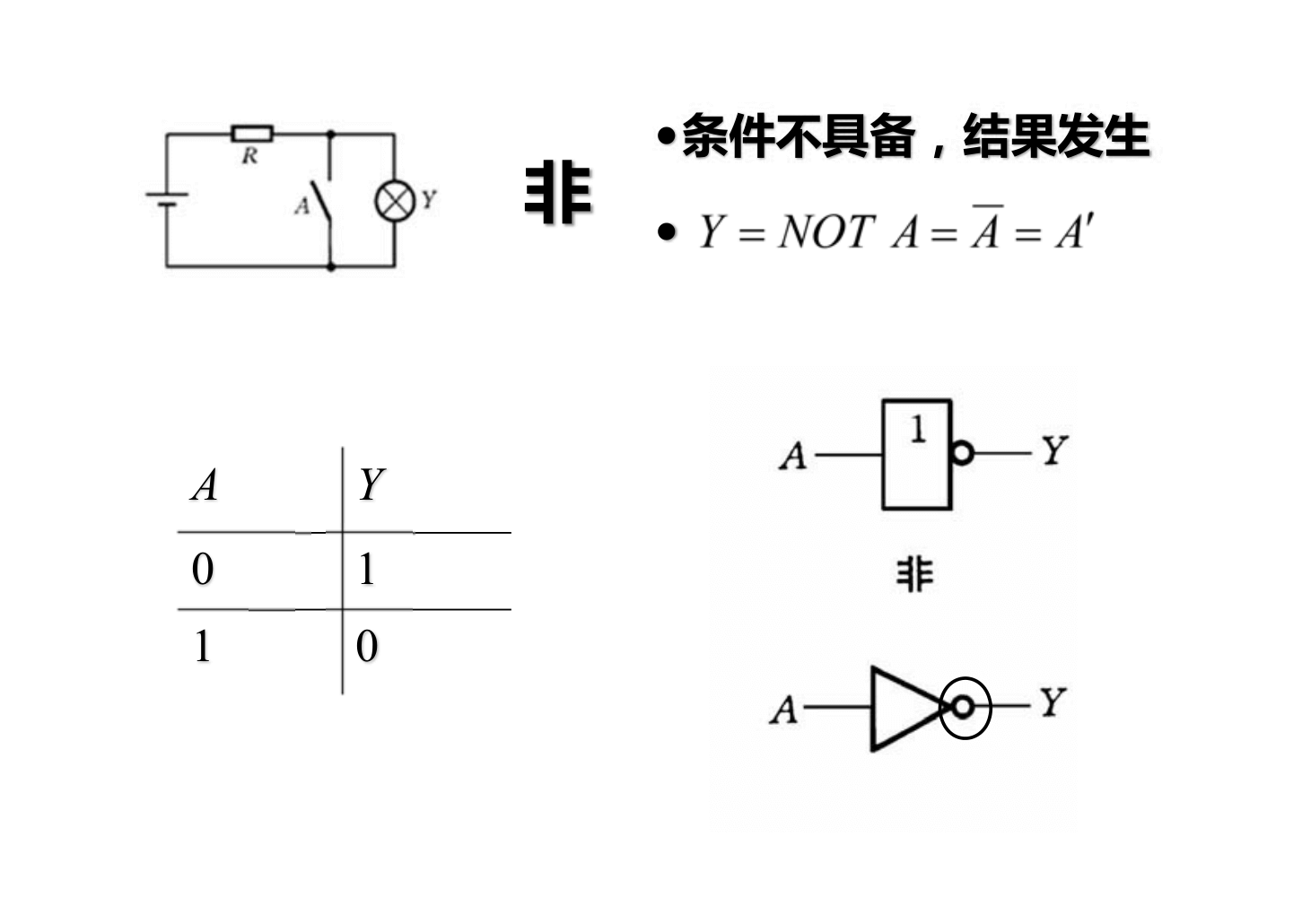
Gate Circuits
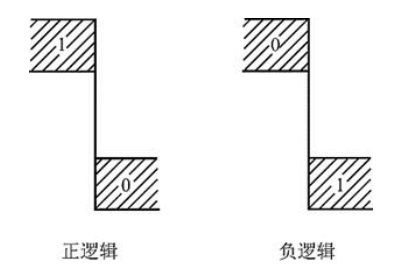
Positive Logic and Negative Logic
If logic 1 is represented by a high voltage level and logic 0 is represented by a low voltage level, this representation method is called positive logic; otherwise, it is called negative logic.
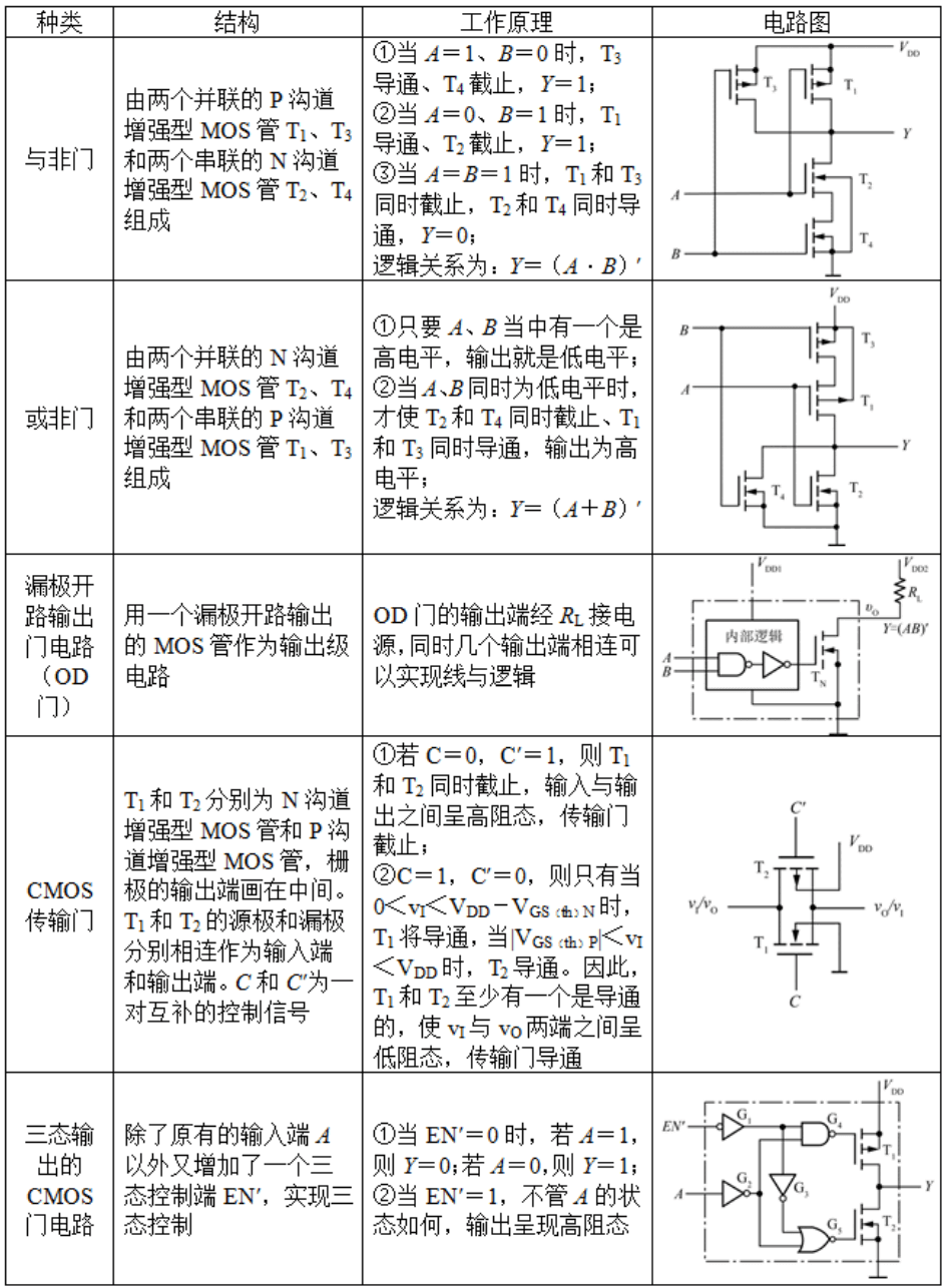
CMOS Gate Circuits
References and Acknowledgements
- "Coding: The Language Hidden Behind Computer Software and Hardware"
Original: https://wiki-power.com/ This post is protected by CC BY-NC-SA 4.0 agreement, should be reproduced with attribution.
This post is translated using ChatGPT, please feedback if any omissions.