Power Solution (Buck) - XL2009E1
XL2009E1 is a Buck chip from Core Dragon with a maximum input of 36V, output of 3A, and fixed frequency of 180kHz. It has overcurrent protection, and the frequency will drop to 48kHz in the event of a short circuit.
Project Repository: Collection_of_Power_Module_Design/DC-DC(Buck)/XL2009E1
Key Features
- Topology: DC/DC (Buck)
- Device Model: XL2009E1
- Package: SOP8L
- Input Voltage: 8-36V
- Output Voltage: 1.25-32V
- Minimum Input-Output Difference: 0.3V
- Maximum Duty Cycle: 100%
- Operating Frequency: Fixed at 180kHz
- Maximum Output Current: 3A
- Efficiency (Input 12V, Output 5V@2.1A): 89%
- Reference Price: ¥2.1
- Other Features:
- Output Constant Current Loop
- Built-in Short Circuit Protection
- Built-in Current Limit Protection
Typical Application Circuit
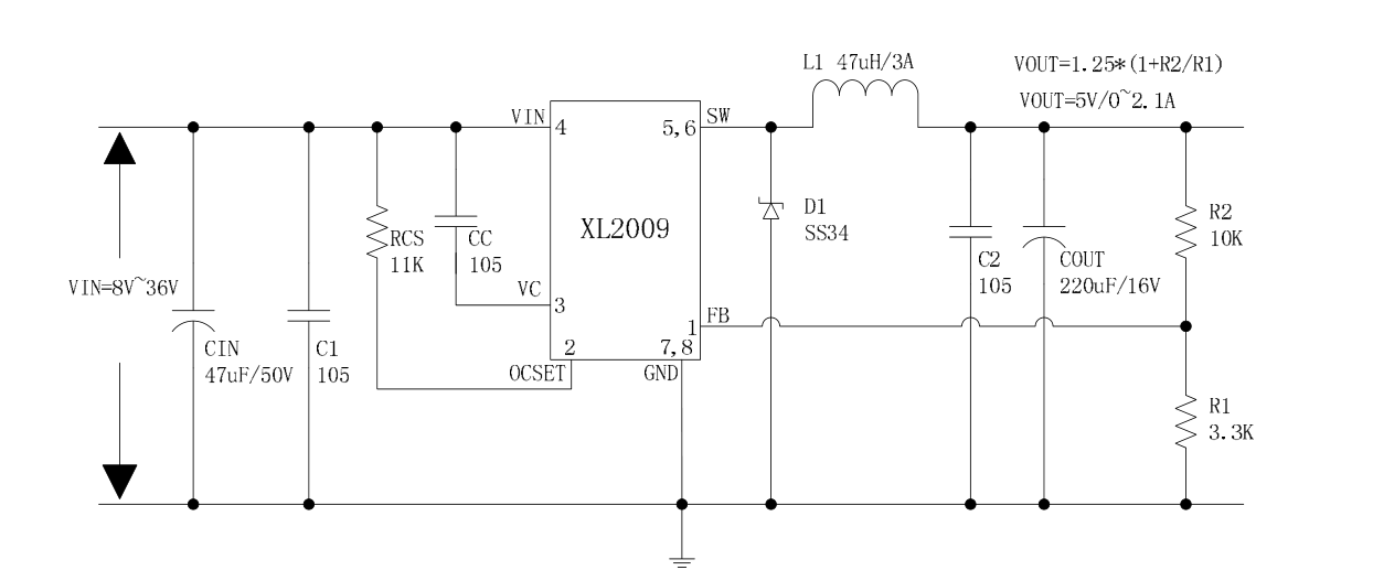
Based on the datasheet, the typical application circuit is as follows (Input 8-36V, Output 5V@2.1A):
Pin Definitions
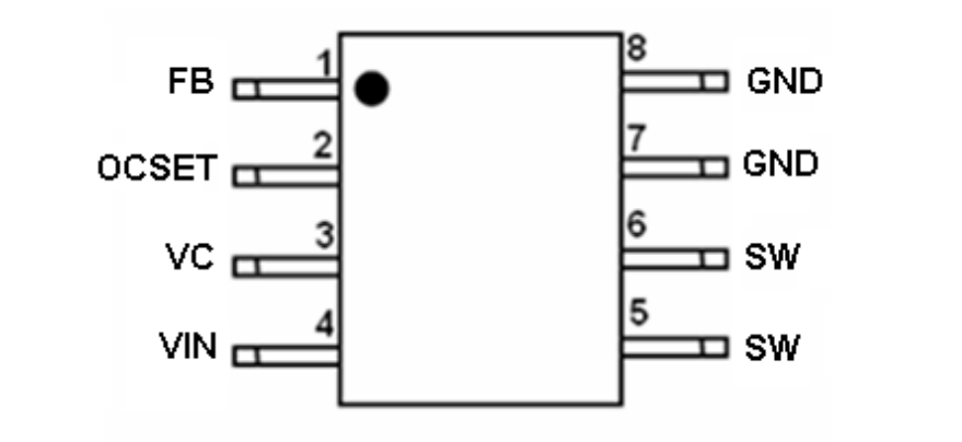
- FB: Feedback input pin, feedback is divided by resistors from \(V_{OUT}\), cannot be directly grounded. The feedback reference voltage is 1.25V.
- OCSET: Output constant current setting pin.
- VC: Bypass capacitor for internal regulator. Generally connected to 1uF to VIN.
- VIN: Power input pin. Input voltage is 8-36V. Requires large decoupling capacitor.
- SW: Buck switch output.
Feature Description
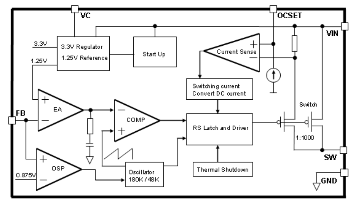
Internal Functional Block Diagram
Output Voltage Regulation
XL2009E1 provides an internal reference voltage of 1.25V. The output voltage is divided by a resistor divider and fed into the FB pin for internal comparison and regulation. It is recommended to use resistors with a deviation of 1% or lower and a temperature coefficient of 100 ppm or lower for the voltage divider. Choosing larger resistor values for the voltage divider helps improve light load efficiency, but if they are too large, the regulator will be more susceptible to noise and voltage errors from the FB input current. It is recommended to use a low-side resistor \(R_1\) value of 4.7k and calculate the high-side resistor \(R_2\) using the formula:
Schottky Diode Selection
The rated breakdown voltage of the diode is preferably 25% higher than the maximum input voltage. For optimal reliability, the rated current of the diode should be equal to the maximum output current of the regulator. In cases where the input voltage is much higher than the output voltage, the average diode current will be lower. In such cases, a diode with a lower average current rating, approximately \((1-D) * I_{OUT}\), can be used. However, the peak current rating should be higher than the maximum load current.
The datasheet of XL2009E1 provides a direct selection table for a 3A diode:
| Input Voltage | Model |
|---|---|
| 20V | SK32 |
| 30V | SK33/30WQ03 |
| 40V | SK34/30WQ04 |
| 50V | SK35/30WQ05 |
| 60V | SK36 |
Parameter Curves
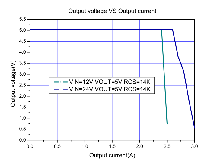
Relationship between output voltage and current:
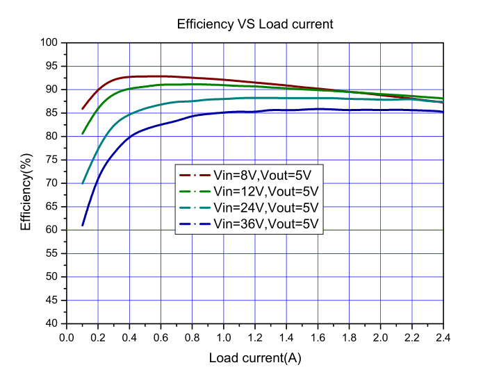
Relationship between efficiency and output current:
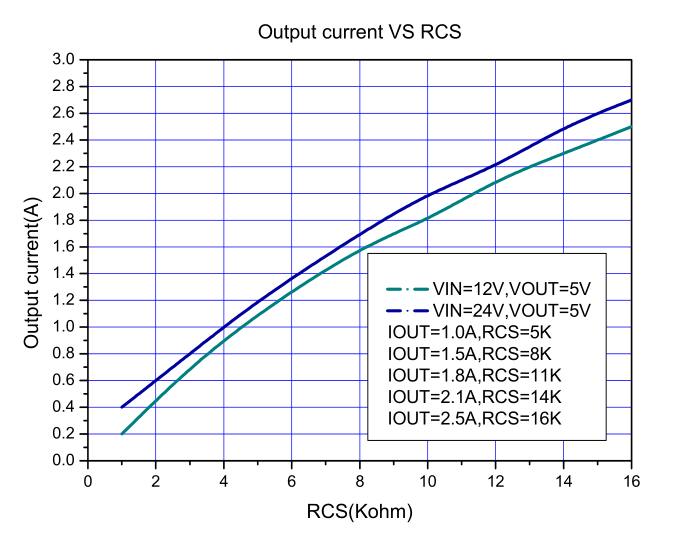
Relationship between output current and RCS resistor (constant current control):
Translate into English:
References and Acknowledgements
Original: https://wiki-power.com/
This post is protected by CC BY-NC-SA 4.0 agreement, should be reproduced with attribution.This post is translated using ChatGPT, please feedback if any omissions.