Power Supply Design - LDO Power Supply Rejection Ratio (PSRR) and Measurement Methods
One of the advantages of Low Dropout Regulators (LDOs) over DC-DC converters is their low output voltage ripple. However, in high-speed circuits, the Power Supply Rejection Ratio (PSRR) of an LDO is also a crucial factor. It is often mistakenly considered a static value, but this article will provide a detailed explanation of PSRR and how to measure it.
Definition of Power Supply Rejection Ratio (PSRR)
The Power Supply Rejection Ratio (PSRR), also known as ripple rejection, can typically be found in an LDO's datasheet. It represents the attenuation from the input to the output of an LDO at a specific frequency, indicating its ripple rejection capability at different frequencies. In high-speed communication circuits like Wi-Fi and Bluetooth, it is essential to use high-speed LDOs with a significant PSRR. This ensures that the chip can respond quickly when it needs to draw a sudden surge of current, preventing the voltage from dropping below the rated value and causing the load to reset. In some cases, a DC-DC converter is used as the primary step-down regulator, and the LDO acts as the secondary step-down or filtering stage. In such scenarios, PSRR must be carefully considered, as DC-DC switching frequencies are typically in the kHz to MHz range, and LDOs must effectively reject ripple above 100kHz.
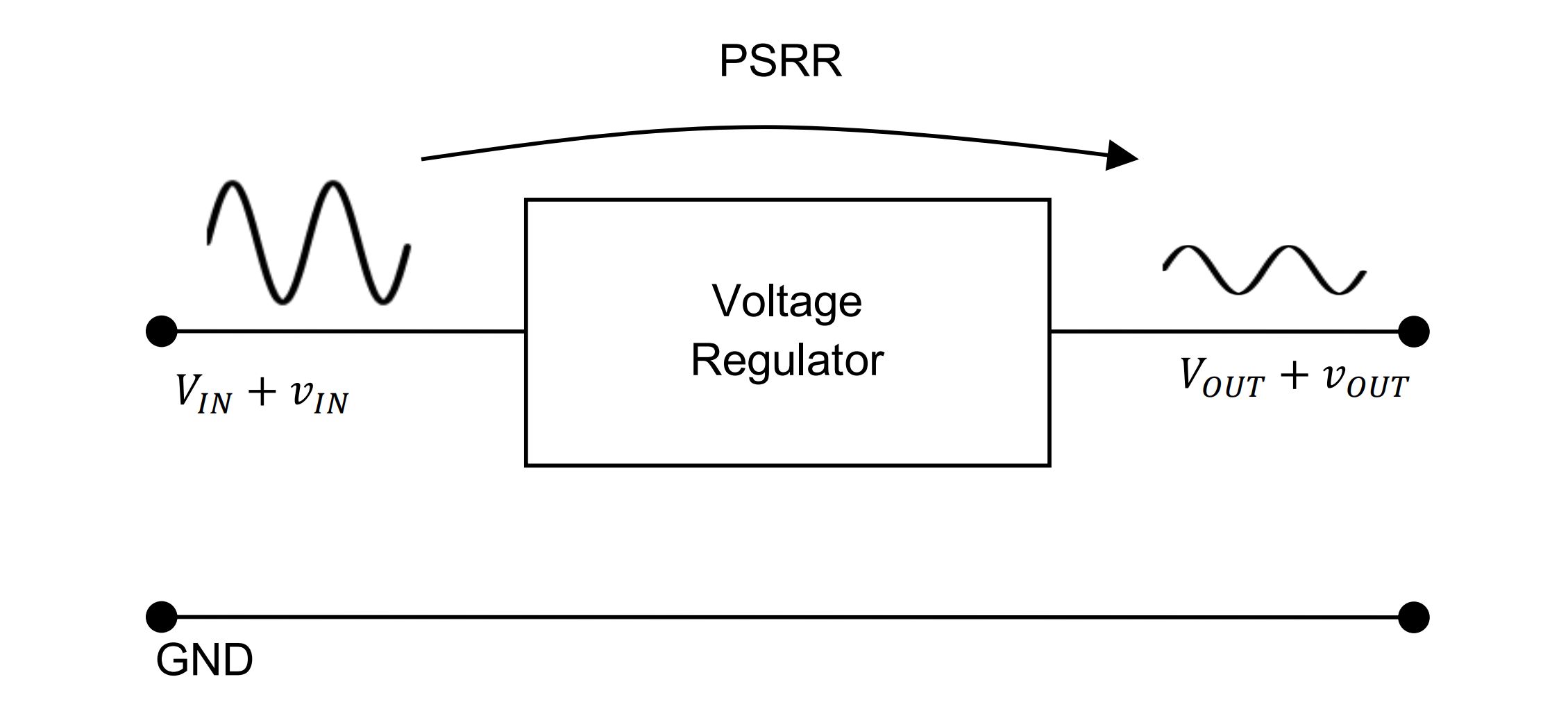
The formula for Power Supply Rejection Ratio (PSRR) is given by:
Where \(V_{rp(in)}\) represents the input ripple, and \(V_{rp(out)}\) represents the output ripple. High-speed LDOs typically have a PSRR greater than 60dB, while regular LDOs usually have a PSRR of around 20dB. A 60dB PSRR means that when the input ripple is 1V, the output ripple will be only 1mV.
Let's first examine the ripple rejection curve for a typical LDO (XC6206 series):
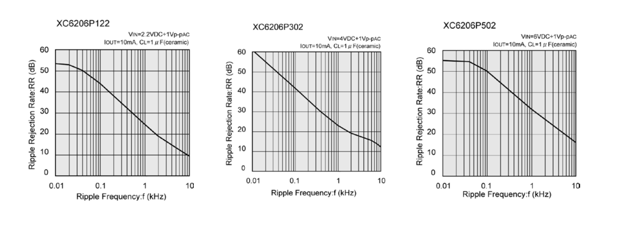
At a frequency of 1kHz, the XC6206P302 has a ripple rejection ratio of approximately 23dB.
Now, let's take a look at the ripple rejection curve for a high-speed LDO (XC6217x302):
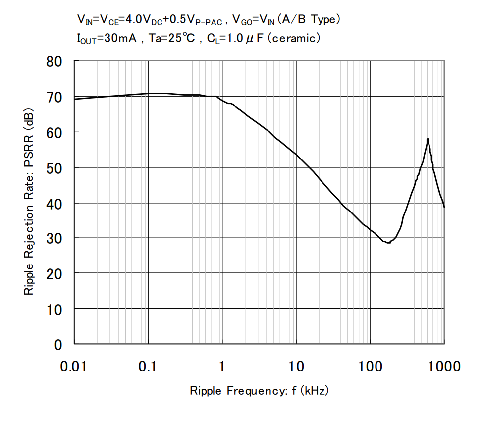
At a frequency of 1kHz, the XC6217x302 exhibits a ripple rejection ratio of about 68dB.
Measurement Methods for Power Supply Rejection Ratio (PSRR)
Measuring the Power Supply Rejection Ratio (PSRR) involves two parts: input injection and output measurement. By following the methods below and recording the input and output voltage ripple, you can calculate the PSRR value using the formula.
Input Injection
Signal Generator
Use a signal generator to directly generate a sine wave and connect it to the input of the LDO. This method is limited by the output current of the signal generator (e.g., the peak output current of a DG4062 is 1.65A under a 100kHz sine wave).
Operational Amplifier
An operational amplifier is used to superimpose AC ripple on the DC voltage of the power source. The choice of the operational amplifier must meet several basic requirements:
- The operational amplifier's bandwidth must cover the LDO testing range.
- The operational amplifier's maximum output current should be no less than the LDO's maximum output current.
- The operational amplifier's output voltage range should cover the LDO's input voltage range.
You can design an adder as shown in the schematic below:
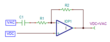
Here, R1 and R2 are equal, and the lowest cutoff frequency is determined by C1 and R1, while the highest cutoff frequency is determined by the bandwidth of the operational amplifier.
Signal Generator + Operational Amplifier
Using an operational amplifier as a voltage follower for the signal generator can overcome the limitations of the signal generator's drive current.
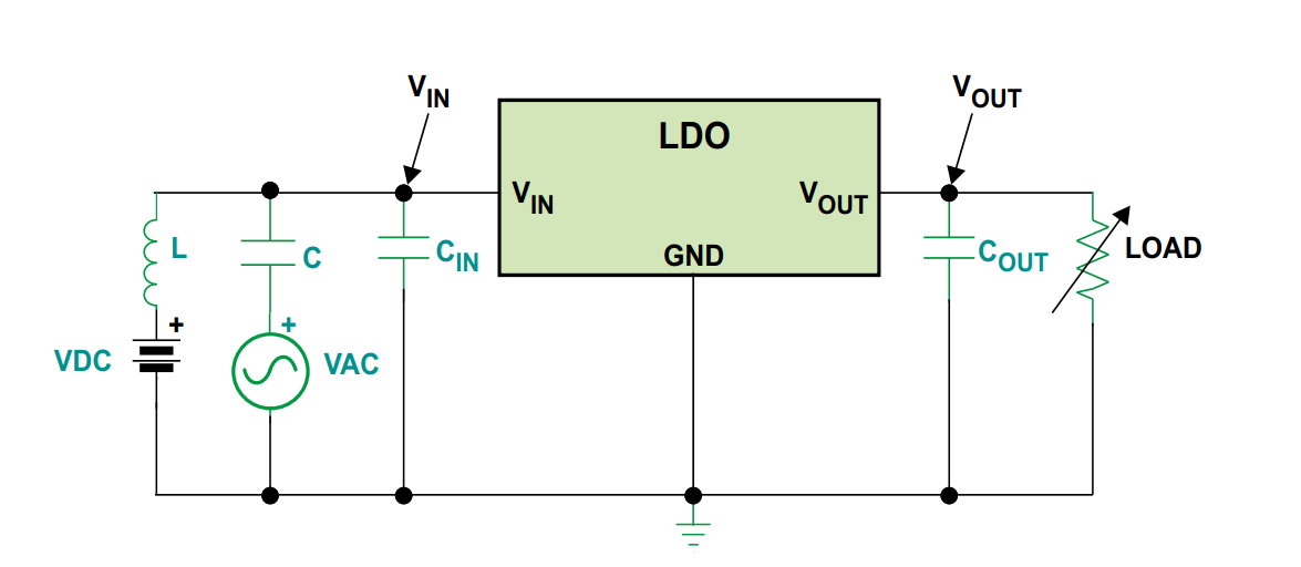
LC Node Method
Utilize inductors and capacitors to combine DC voltage and AC voltage as the input to the LDO:
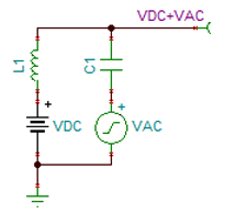
In this context, capacitor C1 serves to prevent high-frequency pulse interference from VAC on VDC, while inductor L1 prevents VDC from short-circuiting VAC. The combination of LC isolates these two power sources.
The highest frequency of this circuit is determined by the inductor L1 and capacitor C1, while the lowest frequency is determined by C1.
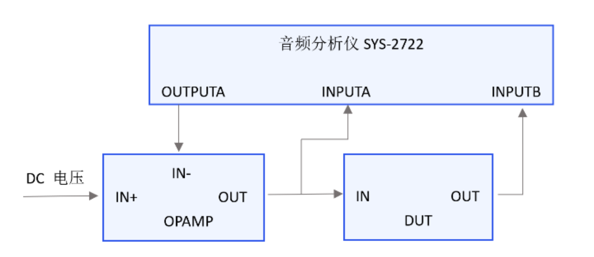
Audio Analyzer (Audio Precision)
The audio analyzer itself lacks the capability to generate DC voltage and has limited driving capacity. Therefore, it requires a high-bandwidth operational amplifier (op-amp) with a substantial current output to superimpose the AC ripple it generates onto the DC voltage of the power source. Afterward, this combined signal is connected to the input of the Low Drop-Out (LDO) regulator. However, due to the bandwidth limitations of the audio analyzer, it cannot measure Power Supply Rejection Ratio (PSRR) beyond 100kHz.
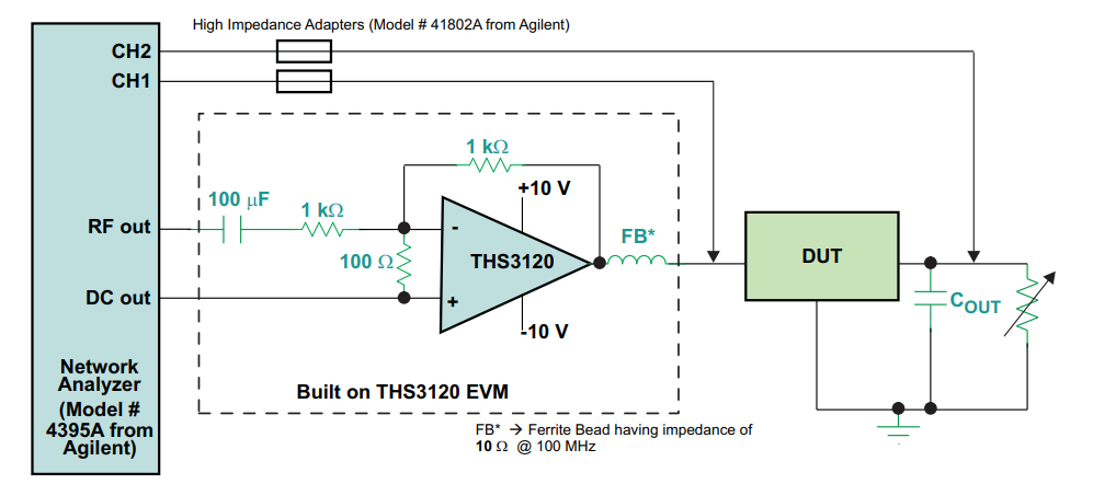
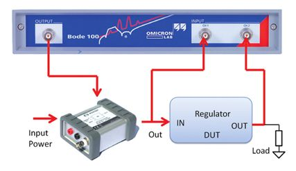
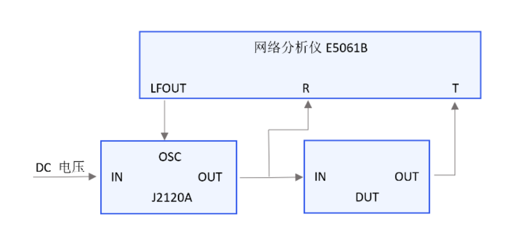
Specialized Injector
This method involves the use of a dedicated input injector (e.g., J2120A), with a bandwidth of 10Hz-10MHz, a maximum DC voltage of 50V, and a maximum output current of 5A. It allows for the direct superimposition of AC ripple and DC voltage from the power source. However, the input voltage is subject to some attenuation after passing through the injector. This setup is typically used in conjunction with a network analyzer to separately measure the input and output voltage ripple:
Output Measurement
Oscilloscope
A standard oscilloscope can measure millivolt-level voltages. When the LDO's PSRR is not very high, around 40-50dB, and the peak-to-peak value of the input AC voltage is 1V, the same frequency AC voltage at the LDO's output will typically range from 3mV to 10mV, making it directly measurable with an oscilloscope.
Oscilloscopes are not suitable for measuring high-PSRR LDOs as they may struggle to precisely measure very small output ripple voltages.
Op-Amp + Oscilloscope
When the LDO's PSRR exceeds 50dB, and the output ripple amplitude is typically less than 1mV, using an oscilloscope for direct measurement becomes impractical. In such cases, it's possible to consider using an operational amplifier (op-amp) to amplify the LDO output AC voltage by 100 times or more. When designing the op-amp circuit, you need to consider:
- Removing the DC voltage from the LDO output.
- Ensuring that the noise generated by the amplification circuit is significantly lower than the amplified AC voltage.
- Keeping the op-amp's input offset voltage within acceptable limits to avoid generating a large DC voltage at the output.
- Ensuring that the op-amp's bandwidth meets the frequency range of the LDO's PSRR measurement.
The design of the amplification circuit can be seen here:
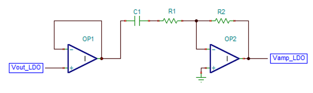
The lower cutoff frequency of this circuit is determined by C1 and R1, while the upper cutoff frequency is determined by the op-amp's bandwidth.
Spectrum Analyzer / Network Analyzer
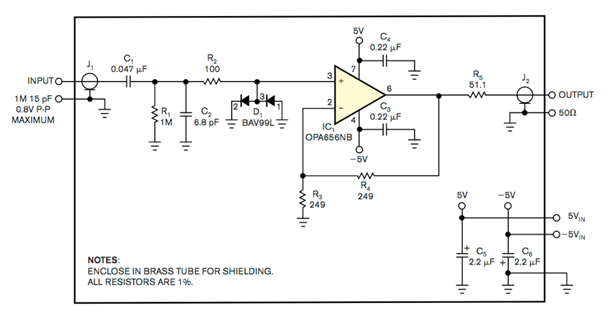
A spectrum analyzer can measure microvolt-level voltage signals and can be used in conjunction with high-impedance input probes to measure the LDO output AC voltage. If high-impedance probes are unavailable, you can set up an op-amp circuit like this:
Measurement Considerations
- When conducting tests, it's important to first observe the AC voltage waveform at the input of the LDO using an oscilloscope to ensure it's normal.
- Following the data sheet, it's advisable to add the appropriate decoupling capacitors to the LDO circuit. However, when testing with an op-amp method, it's necessary to remove the input capacitor of the LDO to avoid instability.
- If using an injector and experiencing voltage attenuation at the output, the voltage may need to be appropriately increased.
- It's recommended not to use an electronic load for the output of the LDO; instead, use a power resistor.
- To reduce noise, use a ground-spring probe for output measurements, as shown below:
References and Acknowledgments
- Reducing High-Speed Signal Chain Power Supply Issues
- LDO Basics: Power Supply Rejection Ratio
- Simplified LDO PSRR Measurement
- LDO PSRR Measurement
- LDO PSRR Measurement · Electronic Study Society
- Power Supply Rejection Ratio (PSRR) Measurement
- Some Insights on DC-DC Transient Testing 🚧
[Placeholder 1]
[Placeholder 2]
This post is translated using ChatGPT, please feedback if any omissions.