HAL Library Development Notes - TIM General Timer
In the previous article, we provided a brief introduction to the three categories of timers in STM32F4 and elaborated on the basic timer. In this article, we will continue by discussing the general timer.
Basic Principles
In STM32F4, the general timers include TIM2-TIM5 and TIM9-TIM14.
Features of General Timers
In STM32F4, the general timers exhibit the following features:
- 16/32-bit increment, decrement, and increment/decrement auto-reload counters.
- 16-bit programmable prescaler for dividing the counter clock frequency (with a division factor ranging from 1 to 65536).
- 4 independent channels, each usable for:
- Input capture
- Output comparison
- PWM generation (edge and center-aligned modes)
- Single-pulse mode output
- Synchronization of multiple timers through external signal control.
- Generation of interrupts/DMA requests upon the occurrence of events such as:
- Update: Counter overflow/underflow, counter initialization (triggered by software or internal/external events).
- Trigger events (counter start, stop, initialize, or count through internal/external triggers).
- Input capture
- Output comparison
- Support for incremental (quadrature) encoder and Hall sensor circuits.
- External clock trigger input or per-cycle current management.
Common Timer Function References
The following are common timer function references, similar to those used for basic timers.
- HAL_TIM_Base_Init(): Initialize the timer's basic time unit.
- HAL_TIM_Base_DeInit(): Disable the timer, opposite of initialization.
- HAL_TIM_Base_MspInit(): MSP initialization function automatically called during timer initialization.
- HAL_TIM_Base_MspDeInit(): The opposite of the previous function.
- HAL_TIM_Base_Start(): Start the timer.
- HAL_TIM_Base_Stop(): Stop the timer.
- HAL_TIM_Base_Start_IT(): Start the timer in interrupt mode.
- HAL_TIM_Base_Stop_IT(): Stop the timer in interrupt mode.
- HAL_TIM_Base_Start_DMA(): Start the timer in DMA mode.
- HAL_TIM_Base_Stop_DMA(): Stop the timer in DMA mode.
Generating 1 kHz PWM with General Timer
In this experiment, we will use a general timer to generate a 1 kHz PWM signal with a 50% duty cycle, which can be displayed using an oscilloscope.
Configuring the General Timer in CubeMX
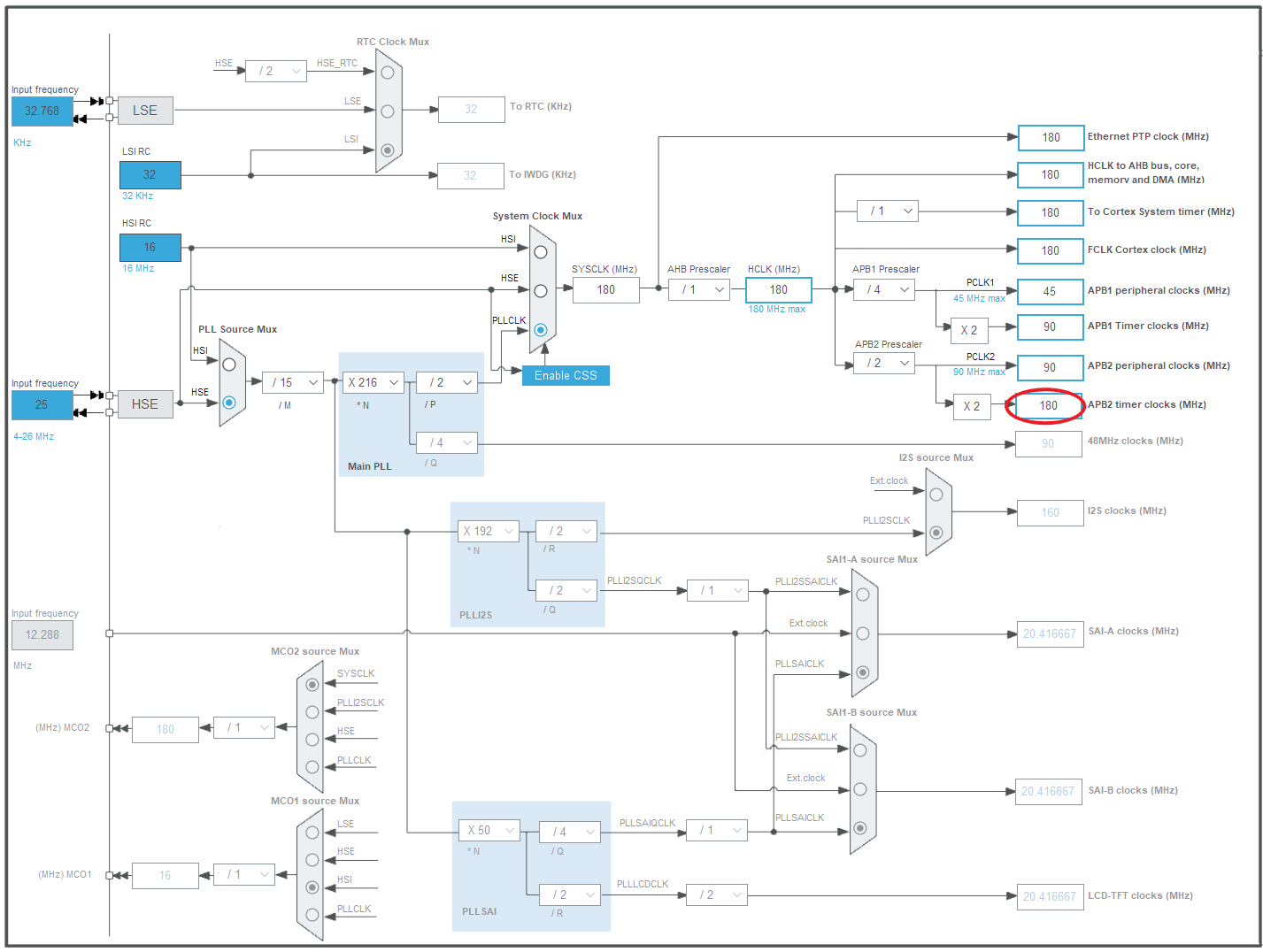
First, open the Clock Configuration clock tree configuration page. Since the general timer is mounted on the high-speed APB2 bus, find and note the clock frequency of APB2 Timer clocks (180 MHz):

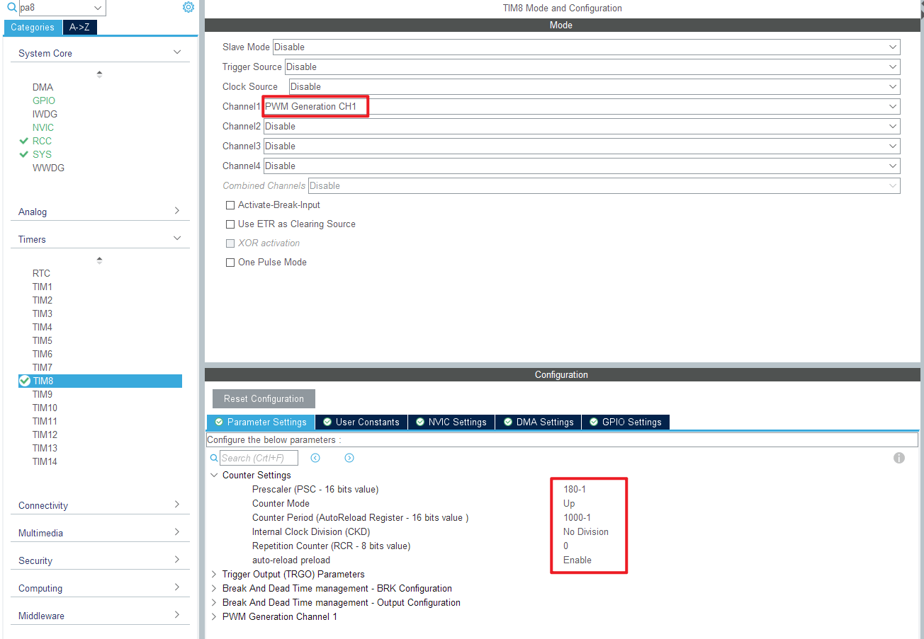
Next, go to the Timer section on the sidebar and select TIM8. Set channel 1 (Channel 1) for PWM generation (PWM Generation CH1). To generate a 1 kHz PWM square wave, configure the following parameters:
- Prescaler: 180-1
- Counter Mode: Up (starts from 0 and counts up to the prescaler value before overflowing)
- Counter Period: 1000-1
- Auto-reload preload: Enable (automatically reloads the initial value upon overflow)

In this case, we have chosen a clock source of 180 MHz. Therefore, set the prescaler to 180-1 = 179, which results in a division of 1 MHz. Set the counter period to 1000-1 = 9999, achieving a frequency of 1 kHz.
Configuring the General Timer in the Code
In main.c, enable the timer:
Note: Please replace [to_be_replace[x]] with the actual content you want to include in your translation.
// Start PWM on TIM8, Channel 1
HAL_TIM_PWM_Start(&htim8, TIM_CHANNEL_1);

// Set the duty cycle to 500 (50% for 500 Hz/1 kHz)
__HAL_TIM_SetCompare(&htim8, TIM_CHANNEL_1, 500);

/* USER CODE END 2 */
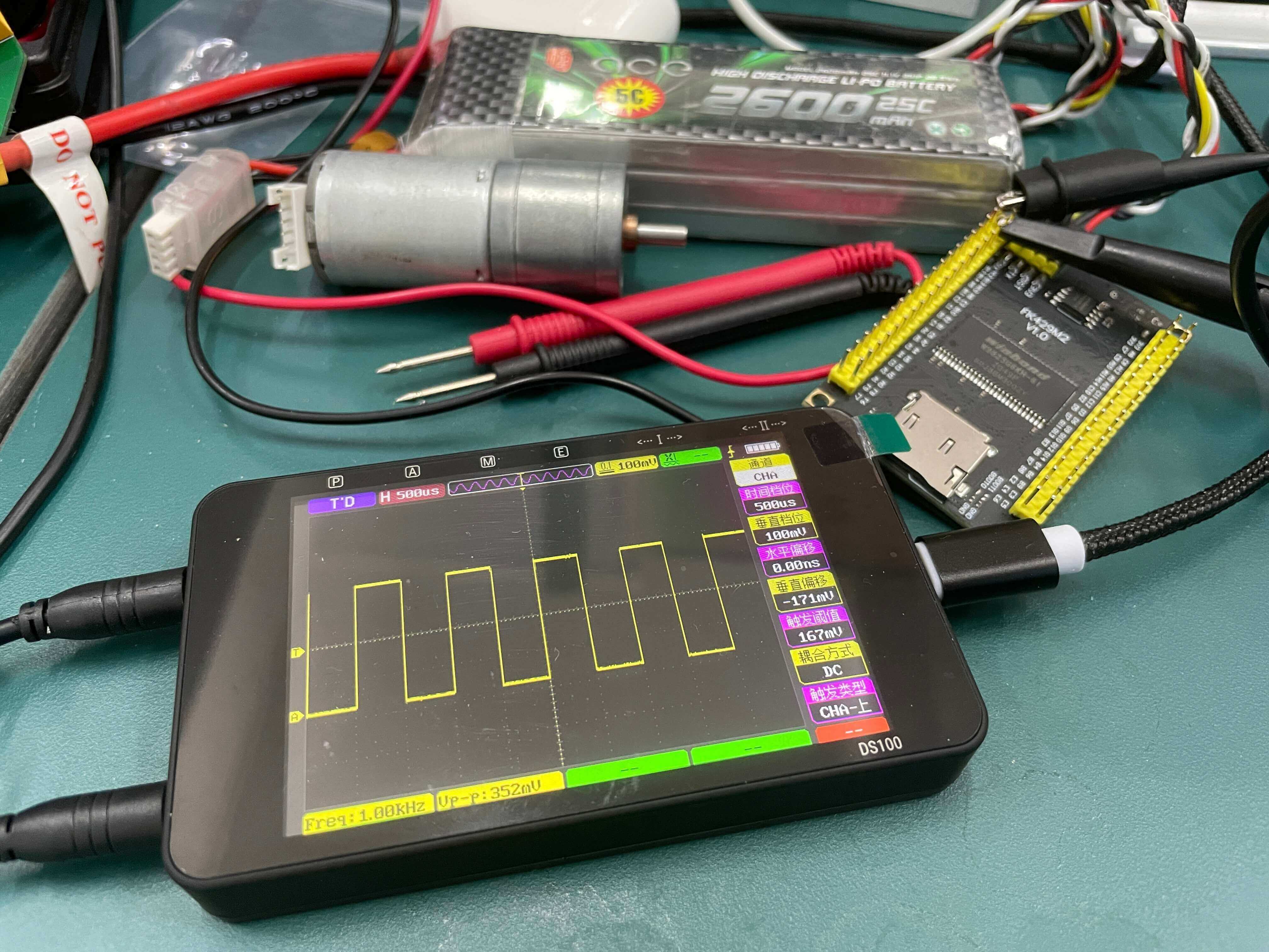
After compiling and flashing, you can observe the waveform using an oscilloscope:

References and Acknowledgments
Original: https://wiki-power.com/ This post is protected by CC BY-NC-SA 4.0 agreement, should be reproduced with attribution.
I have maintained the original markdown format while providing a professional and fluent translation. If you have any further requests or questions, please feel free to ask.

> This post is translated using ChatGPT, please [**feedback**](https://github.com/linyuxuanlin/Wiki_MkDocs/issues/new) if any omissions.