OrCAD Configuration and Tips
Note: This article is based on Cadence OrCAD Capture CIS.
Basics
To draw schematics, use OrCAD Capture CIS (Start Menu -> Cadence -> Capture CIS). To design PCBs, use Allegro PCB Designer (Start Menu -> Cadence -> PCB Editor).
In general, you can encompass the entire project with a .DSN file, which will automatically generate .opj and other schematic files when opened. If you are using Git for version control, consider adding the following to your .gitignore:
# From the original gitignore

#############
## Allegro
#############

# Ignore log files
*.log
*.log,1
*.log,2
*.log,3

*.dml
*.lst

# Ignore event logging for Allegro operations
*.jrl
*.jrl,1

*.tag

# Report files
*.rpt

*.cfg
*.cfg,1

*.lck

# Report files
*.txt
*.txt,1
*.txt,2

# Exclude XY data
!place_txt.txt

# DXF import files
*.cnv

# Exclude Gerber parameter file
!art_param.txt

# Folder
# Exclude the entire folder
/signoise.run/

#############
## OrCAD
#############
*.dbk
*.opj
*.DRC
*.DSNlck

# Ignore netlists
allegro/
Some Settings
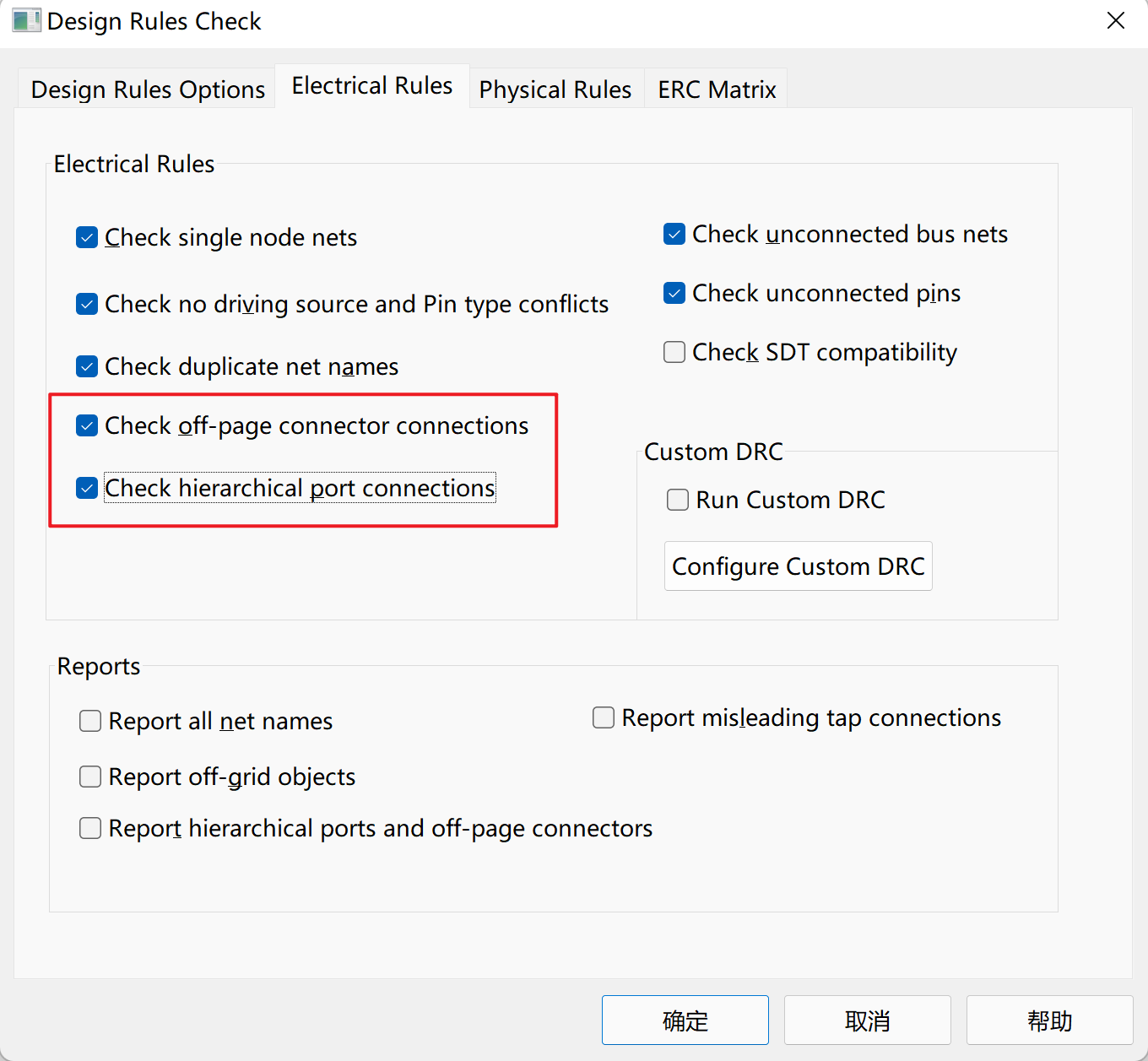
DRC Settings:

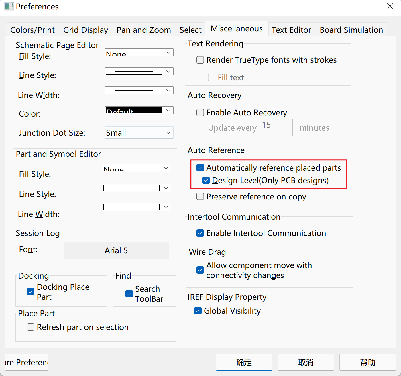
Automatically rename reference designators when copying components:

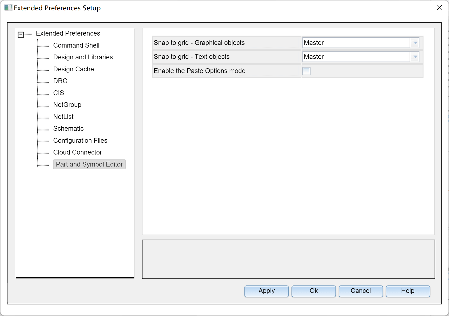
Snap components to the grid while moving text:

Tip: When using the CIP library and encountering the "not found in the configured library lists" error, check for spaces in the path.
- Mouse Wheel Zoom:
Options-Preferences…-Pan and Zoom- Set bothZoom Factorvalues to 1.1. - Refresh Schematic on Part Placement:
Options-Preferences…-Miscellaneous-Place Part- Check "Refresh part on selection." - Set Grid Spacing:
Options-Preferences…-Grid Display-Grid Spacing- Set it to 1/2.
Keyboard Shortcuts
- Draw wires:
W - Cancel:
ESC - Route bus:
F4 - Place net label:
N - Rotate / Horizontal mirror / Vertical mirror components:
R/H/V - Open CIS panel:
Z - Place power / ground:
F/G - No connect:
X - Filter:
Ctrl+I - Multi-select elements: Hold
Ctrlwhile selecting - Copy and automatically increment reference designators: Hold
Ctrland drag components - Move the schematic with the mouse as the pivot: Hold
Cand drag the mouse - Place bus:
E - Place text:
T
Errors and Solutions
- Unable to drag components: Generally, a restart can resolve this issue.
Tips
Difference Between Off-Page and Port
Off-page is typically used in flat schematics, while port is generally used in hierarchical schematics.
DRC Check
1. Click to select the entire project in the file tree.
2. Click on the toolbar `Tools` - `Design Rules Check...`
3. Check the boxes for `Run Physical Rules` and `View Output`.
4. Click OK, and a report will be generated and automatically opened.

## References and Acknowledgments

- [Quick Start Guide for Cadence](https://blog.csdn.net/ReCclay/article/details/101225359)
- [OrCAD Capture Tutorial](https://resources.orcad.com/orcad-capture-tutorials)
- [Resolution for Cadence Software Font Blurriness on High-Resolution Notebooks](https://blog.csdn.net/qq_34338527/article/details/108846792)
This post is translated using ChatGPT, please feedback if any omissions.