Componentes básicos - Resistencias
Selección de resistencias
En general, se deben considerar los siguientes cuatro factores:
- Valor de resistencia: depende de las necesidades del circuito de aplicación específico.
- Precisión: generalmente es del 1%. Si se utiliza en un circuito de detección de corriente (Rsense), se prefiere una resistencia de baja resistencia y alta potencia para lograr una mayor precisión.
- Potencia nominal: debe cumplir con una disminución del 50%. Consulte la tabla a continuación para conocer la potencia correspondiente a cada encapsulado.
- Dimensiones: las dimensiones están relacionadas con la potencia y la dificultad de fabricación. Se deben tener en cuenta la potencia y la dificultad de fabricación.
- Temperatura de funcionamiento, humedad, etc.: factores a considerar en situaciones específicas.
- Coeficiente de temperatura: debe tenerse en cuenta si se utiliza en aplicaciones de alta precisión (sensores).
Parámetros de los encapsulados SMD
| Sistema Imperial | Sistema Métrico | Largo (mm) | Ancho (mm) | Alto (mm) | Potencia nominal (W) | Voltaje máximo (V) |
|---|---|---|---|---|---|---|
| 0201 | 0603 | 0.60±0.05 | 0.30±0.05 | 0.23±0.05 | 1/20 | 25 |
| 0402 | 1005 | 1.00±0.10 | 0.50±0.10 | 0.30±0.10 | 1/16 | 50 |
| 0603 | 1608 | 1.60±0.15 | 0.80±0.15 | 0.40±0.10 | 1/10 | 50 |
| 0805 | 2012 | 2.00±0.20 | 1.25±0.15 | 0.50±0.10 | 1/8 | 150 |
| 1206 | 3216 | 3.20±0.20 | 1.60±0.15 | 0.55±0.10 | 1/4 | 200 |
| 1210 | 3225 | 3.20±0.20 | 2.50±0.20 | 0.55±0.10 | 1/3 | 200 |
| 1812 | 4832 | 4.50±0.20 | 3.20±0.20 | 0.55±0.10 | 1/2 | 200 |
| 2010 | 5025 | 5.00±0.20 | 2.50±0.20 | 0.55±0.10 | 3/4 | 200 |
| 2512 | 6432 | 6.40±0.20 | 3.20±0.20 | 0.55±0.10 | 1 | 200 |
Valores de resistencia
Método de marcado
- Notación de tres dígitos: \(XXY = XX * 10^Y\)
- Por ejemplo, una resistencia con un marcado de 272 tiene un valor real de \(27 * 10^2=27 * 100=2.7k\)
- Notación de cuatro dígitos: \(XXXY = XXX * 10^Y\)
- Notación de letras para indicar la posición del punto decimal:
Rindica el punto decimal.- Por ejemplo, una resistencia con un marcado de 5R6 tiene un valor real de 5.6 Ω
M,k,mtambién se pueden utilizar para indicar el punto decimal, representandoMΩ,kΩ,mΩ, respectivamente.
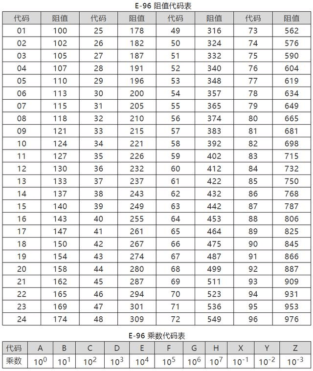
- Notación de código de multiplicador de tres dígitos: en
XXY,XXrepresenta el código del número significativo yYindica la potencia de 10. Consulte la tabla de valores de resistencia estándar a continuación.- Por ejemplo, una resistencia con un marcado de 01C tiene un valor real de \(100*10^2=10 kΩ\)
Valores de resistencia estándar
Según las convenciones y normas establecidas, la serie más utilizada es la serie E96, cuyos valores de resistencia y códigos de multiplicador se muestran a continuación:
Fallas de las resistencias
Según la probabilidad de ocurrencia, las fallas se clasifican de la siguiente manera:
- Circuito abierto: defecto o degradación de la película de resistencia; puede ocurrir cuando se produce un impacto de alta potencia.
- Desviación de valor de resistencia fuera de especificación: puede ocurrir después del envejecimiento.
- Rotura de pines: defectos en el proceso de soldadura, contaminación de las soldaduras; puede ocurrir cuando los pines de la resistencia de montaje en orificio se doblan repetidamente.
- Quemadura: puede ocurrir cuando se trabaja durante mucho tiempo por encima de la potencia nominal, lo que puede provocar un circuito abierto.
- Problemas de soldadura: soldaduras en falso y otros problemas.
- Rotura de cables y circuito abierto: puede ocurrir debido a tensiones mecánicas o impactos de alta potencia.
Uso de resistencias de 0 ohmios
- When used as a jumper, it crosses over areas where no traces are laid.
- Used as a shorting socket.
- Single-point connection between digital ground and analog ground (sometimes also using inductors or ferrite beads).
- Reserved resistance for debugging purposes.
Overcurrent capability of 0-ohm resistors in different packages (generally used with a 50% reduction in rated current):
| Package | Rated Current (Maximum Current) /A |
|---|---|
| 0201 | 0.5 (1) |
| 0402 | 1 (2) |
| 0603 | 2 (3) |
| 0805 and up | 2 (5) |
Applications of Resistors
Voltage Divider Circuit
Resistors are connected in series for voltage division, with the following circuit characteristics:
- The current through each resistor is the same, i.e., the current in each resistor is equal, i.e., \(I = I_1 = I_2 = I_3\).
- The total voltage is equal to the sum of the voltage drops across each resistor, i.e., \(V = V_1 + V_2 + V_3\).
- The total resistance is equal to the sum of the resistances, i.e., \(R = R_1 + R_2 + R_3\).
For example, the feedback pin of a voltage regulator is generally connected to a voltage divider circuit consisting of two resistors, which provides an output voltage value close to the internal reference voltage.
Current Divider Circuit
Resistors are connected in parallel for current division, with the following circuit characteristics:
- The voltage across each branch is the same.
- The total current is equal to the sum of the branch currents, i.e., \(I = I_1 + I_2 + I_3\).
- The reciprocal of the total resistance is equal to the sum of the reciprocals of the branch resistances, i.e., \(\frac{1}{R} = \frac{1}{R_1} + \frac{1}{R_2} + \frac{1}{R_3}\).
In practical circuit design, this is often used to protect resistors connected in parallel between the collector and emitter of a transistor. In cases where the power of a linear power regulator is insufficient, resistors can also be used between the input and output terminals to increase the output current.
Current Limiting Circuit
Generally used for current limiting of LEDs. A resistor is connected in series with the circuit where the LED is located to determine the resistance value based on the forward voltage drop of the LED (generally 0.7 V) and the rated current of the LED. It should be noted that the calculated actual operating current should be less than the rated operating current of the LED.
Current limiting circuits can also be used in hot-swappable circuits.
Impedance Matching Circuit
The purpose of impedance matching is to maximize the power obtained by the load, i.e., the load resistance is equal to the source resistance. The derivation process is as follows:
Assuming the load resistance is R, the electromotive force of the power source is U, and the internal resistance is r, the current through R is:
It can be seen that the smaller R is, the larger the current. The voltage across R is:
The larger R is, the larger the output voltage \(U_R\) is. The power of R is:
Since r is constant, when R=r, \(\frac{(R-r)^2}{R}=0\), and the maximum power \(P_{max}=\frac{U^2}{4r}\) can be obtained.
RC Charging and Discharging Circuit
\(\tau=RC\) (if the units of R and C are Ω and F, the unit of the result is s).
The RC circuit can be regarded as a delay circuit or a filtering circuit, which filters both the rising and falling edges of the pulse signal, making it smooth. Different rise times can be achieved by adjusting the values of R and C.
Pull-up and Pull-down Circuit
Pull-up is used to clamp an uncertain signal to a high level (while also acting as a current limiter); pull-down does the opposite.
Generally, resistors below 50 Ω are strong pull-up/pull-down, and resistors above 100 kΩ are weak pull-up/pull-down.
Other Circuits
- Peripheral circuits of operational amplifiers.
- Interference suppression circuits to improve surge voltage capability.
- Load circuits (to prevent circuit no-load).
References and Acknowledgements
- "《Hardware: 100,000 Whys - Passive Components》"
- Table of SMD Resistor Packages, Dimensions, and Power Ratings
- Power Master Class Series (2) | Things You Don't Know About Resistors and Capacitors
Dirección original del artículo: https://wiki-power.com/ Este artículo está protegido por la licencia CC BY-NC-SA 4.0. Si desea reproducirlo, por favor indique la fuente.
Este post está traducido usando ChatGPT, por favor feedback si hay alguna omisión.