RF - Components and Systems - Capacitors
Capacitors find wide applications in RF, including bypassing, interstage coupling, resonant circuits, and filtering.
Parallel Plate Capacitors
A capacitor is any device composed of two conductive surfaces separated by an insulating material or dielectric. The dielectric can be ceramic, air, paper, mica, plastic, thin film, glass, or oil. The capacitance of a capacitor is the property that allows it to store charge when there is a potential difference between the conductors. Capacitance is measured in units of farads (F).
A capacitor consists of two conductive surfaces separated by an insulating material or dielectric, which is typically made of ceramic, air, paper, mica, plastic, thin film, glass, or oil. Capacitance is the property that allows the storage of electric charge when there is a potential difference between the conductors, and it is expressed as:
Here, the unit of capacitance, \(C\), is the farad (F), and the unit of charge, \(Q\), is the coulomb (C). Due to the large magnitude of the farad, it is often expressed as \(1uF=10^{-6}F\) and \(1pF=10^{-12}F\).
If we know the area of the parallel plates, \(A\), the separation between the plates, \(d\) (in inches), and the dielectric material's permittivity, \(\varepsilon\) (in F/m), the formula for the capacitance of a parallel plate capacitor can be expressed as:
Here, \(\varepsilon_0\) is the permittivity of free space (\(\varepsilon_0=8.854*10^{-12}F/m\)).
Capacitor Equivalent Circuit
Parallel plate capacitors are idealized components. In the real world, the equivalent circuit of a capacitor is as shown in the diagram below:
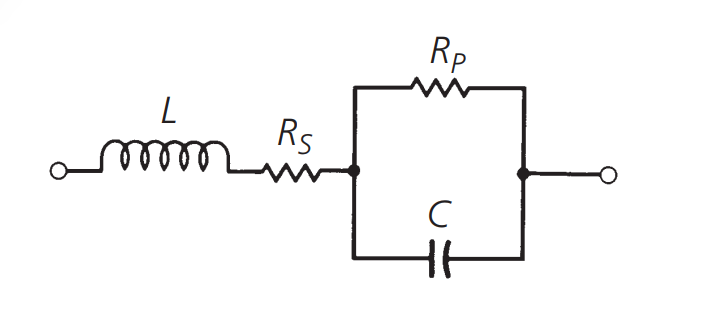
In this diagram, \(C\) represents the capacitor, \(L\) is the lead inductance, \(R_s\) represents the thermal losses denoted by the power factor (PF) or dissipation factor (DF), and \(R_p\) represents the insulation resistance. These parameters are further defined as follows:
Power Factor (PF):
In an ideal capacitor, the AC current leads the applied voltage by 90°. However, in a real capacitor's equivalent circuit with total series resistance (\(R_s + R_p\)), this phase angle, \(\phi\), is smaller. The power factor is a function of temperature, frequency, and dielectric material and is defined by the formula:
Insulation Resistance:
It represents the DC current that flows through the dielectric of the capacitor when a voltage is applied. No material is completely insulating, so there will be leakage current. In the equivalent circuit, this leakage current path is represented by \(R_p\), and its value is typically greater than 100,000 megaohms.
Effective Series Resistance (ESR):
This resistance value is the combined equivalent of \(R_s + R_p\) and is the AC resistance of the capacitor. It is defined by the formula:
Here, \(\omega=2 \pi f\).
Dissipation Factor (DF):
The dissipation factor is the ratio of AC resistance to capacitive reactance and is defined by the formula:
The derived quality factor Q is the reciprocal of the dissipation factor, and a higher Q factor indicates better capacitor performance.
The impact of these imperfections in capacitors can be seen in Figure 1-9. Here, the impedance characteristics of an ideal capacitor correspond to those of a real capacitor. As shown, as the operating frequency increases, lead inductance becomes significant. Finally, at Fr, resonance occurs in series with the capacitor. Beyond Fr, the capacitor behaves like an inductor. Generally, larger capacitors tend to have more internal inductance than smaller ones.
In practical capacitors, the frequency and impedance variation curves affected by these factors are depicted in the following figure:
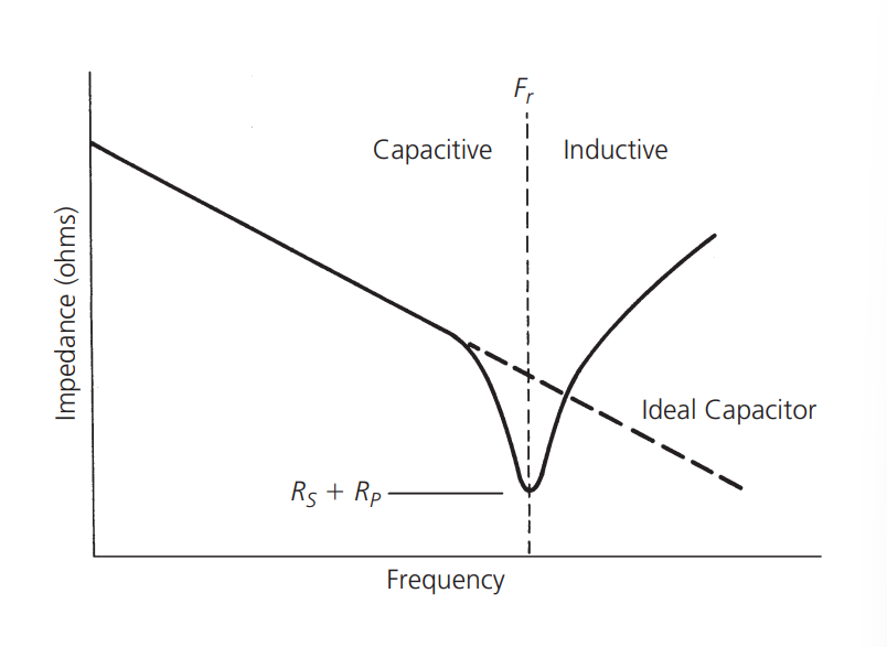
It can be observed that as the frequency increases, the influence of lead inductance becomes more significant. Ultimately, at Fr, the capacitor resonates in series with the inductance. At frequencies above Fr, the capacitor behaves inductively. In general, at a specific frequency, larger capacitors tend to have lower impedance compared to smaller capacitors, as per the formula for reactance \(X_c=\frac{1}{\omega C}\).
However, when it comes to radio frequency (RF) frequencies, the situation may be quite the opposite. At certain higher frequencies, a 100nF capacitor may actually exhibit a higher impedance to the signal than a 330pF capacitor. This is a consideration when designing circuits operating at frequencies exceeding 100 MHz. Using a network analyzer can reveal the impedance of the capacitor at specific frequencies.
Types of Capacitors
Capacitors can be manufactured from various dielectric materials. Common categories include:
(To be continued...)
References and Acknowledgments
- "RF Circuit Design (Second Edition) by Chris Bowick"
Original: https://wiki-power.com/ This post is protected by CC BY-NC-SA 4.0 agreement, should be reproduced with attribution.
This post is translated using ChatGPT, please feedback if any omissions.