Power Integrity Design
Power integrity refers to the quality of power waveforms and focuses on the power distribution network (PDN). It aims to eliminate/reduce the impact of noise on the power supply by considering the overall power supply network of the system. The design goal of power integrity is to control power noise within an acceptable range, provide clean and stable voltage to the chip, maintain it within a small tolerance range (usually within 5%), respond in real-time to rapid changes in current caused by load, and provide a low-impedance return path for other signals.
The main sources of power noise are:
- Output noise of power modules (VRM, including LDO/DC-DC)
- DC resistance and parasitic inductance of traces
- Synchronous switch noise (SSN)
- Power and ground plane resonance noise
- Coupling noise from adjacent power networks
- Coupling noise from other components
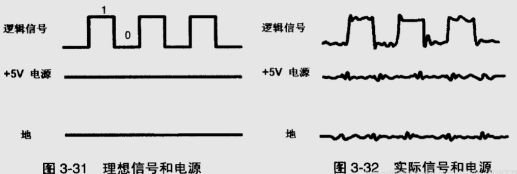
When a large transient current flows through the circuit during logic state switching of many chip pins, it causes fluctuations in the ground plane, resulting in inconsistency between the chip ground and the system ground, known as ground bounce. It also causes a voltage difference between the chip and the system power supply, known as power bounce. When designing PCB stack-up, it is advisable to increase the vertical distance between power planes and reduce the vertical spacing between power and ground planes as much as possible.
Power Integrity Design Strategies
- Pay attention to the current-carrying capacity of vias, traces, and power planes. When multiple power supplies are arranged on one plane, the power plane needs to be divided. The division method should be simple and reasonable, and the size of the divided area should meet the current-carrying capacity requirements.
- Try to pair the power plane with the ground plane and keep them as close as possible.
- Pay attention to the design of decoupling capacitors. Decoupling capacitors have certain distance requirements, known as the decoupling radius. It is recommended to use multiple vias for the fan-out of capacitor pads.
- Pay attention to the impact of synchronous switch noise (ground bounce and power bounce) and consider adding decoupling capacitors. Under the premise of meeting the overall system performance requirements, use smooth drive signals as much as possible (to slow down the rising and falling edges of the driver).
Power Integrity Test Items
Voltage Value (Accuracy)
- Test Instrument: Multimeter
- Test Method: Test separately under no load/full load conditions
- Test Points: Power chip output pins, power pins of the chips being powered
- Acceptance Criteria: Generally within the range of nominal voltage value ±5% (determined based on the voltage requirements of the chip)
Power Noise / Ripple
- Definition
- Ripple: A component that appears between output terminals, synchronized with the input frequency and switching frequency, represented by the RMS value, generally below 0.5% of the output voltage
- Noise: A high-frequency component other than ripple that appears between output terminals, represented by the peak-to-peak value, generally below 1% of the output voltage
- Ripple and Noise: The combination of both, represented by the peak-to-peak value, generally required to be below 2% of the output voltage
- Test Instrument: Oscilloscope
- Test Method
- Test separately under no load/full load conditions
- Ripple: Measure using the ground loop proximity measurement method (proximity measurement) with the oscilloscope set to a bandwidth of 20MHz and a DC offset voltage equal to the voltage accuracy measurement value mentioned above.
- Ripple and Noise: Set the oscilloscope bandwidth to full bandwidth (Full)
- Test Points: Both ends of the output capacitor
- Acceptance Criteria:
- Generally, ripple should be <1% of the output voltage (tested at 20MHz bandwidth, the result can be considered as pure ripple)
- Generally, ripple and noise should be <2% of the output voltage (tested at full bandwidth, the result can be considered as ripple + noise)
- Notes
- Pay attention to the principle of proximity during testing and keep the ground loop as short as possible
- Use a passive probe for testing
- Record the frequency of the ripple during testing for analysis purposes
Voltage Rise and Fall Waveforms
- Test Instrument: Oscilloscope
- Test Method: Set the oscilloscope to trigger on the rising/falling edge, observe the voltage rise and fall waveforms of the switching power supply to identify any issues
- Test Points: Output pins of the power chip, power lines on the system
- Acceptance Criteria:
- The overshoot and undershoot of the power output voltage during voltage rise and fall should generally not exceed 10% of the measured voltage. When testing at the front end of the chip, refer to the general level standards.
- There should not be significant voltage drop during power-up and no significant rebound and overshoot during power-down (the drop and rebound should not cross the chip's startup operating voltage). Evaluate the impact if step phenomena occur.
- If negative voltage occurs, it needs to be discussed based on the actual situation.
- Pay attention to the voltage timing requirements of the chip during power-up and power-down.
- Notes: It is necessary to test various scenarios such as power-up and power-down of the system, plugging and unplugging of the single board, and plugging and unplugging of the power board.
Soft Start Circuit Parameters
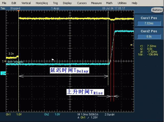
- Test Equipment: Oscilloscope
- Test Method: Use multi-channel testing to observe the time difference after power-on
- Test Points: One circuit before soft start, one circuit after soft start
- Acceptance Criteria:
- Delay Time (\(T_{delay}\)): Generally required to be within the range of 20 to 200ms
- Rise Time (\(T_{rise}\), time for the output voltage to rise from 10% to 90%): The smaller the better, but the surge current must also meet the acceptance criteria
- No multiple oscillation phenomena
- Notes: Need to test the system power-on and power-off, board insertion and removal, and power supply board insertion and removal situations
Power Supply Current and Surge Current
- Test Equipment: Oscilloscope
- Test Method:
- Power Supply Current: Use a current probe to observe the waveform of the power supply current during power-on and the stable waveform after power-on
- Surge Current: Same as above. It is best to test the power-on surge current when the machine is cold (maximum surge current); it is best to test the power-off surge current when the board is fully loaded
- Test Points: Install the current probe on the current path being tested
- Acceptance Criteria:
- The stable value of the power supply current must not exceed 90% of the maximum rated output current
- The surge current value must not exceed 5 times the rated output current (more than 3 times should be noted)
- The current under any condition must be greater than the minimum load of the power supply and meet the requirements of the maximum capacitive load
- Notes:
- Need to test the system power-on and power-off, board insertion and removal, and power supply board insertion and removal situations
- When testing surge current, remove inductive components such as inductors, as inductive devices themselves have the effect of suppressing surge current.
Power Supply Alarm Signal
- Test Method: Create alarm conditions in the system and test the level of the alarm signal
- Test Points: The receiving end of the alarm signal
- Acceptance Criteria: Refer to the specifications of the power supply chip
Current Sharing Parameters of Redundant Power Supplies
- Test Method: Use the method of testing the output current of the test power supply to test the output values of each channel of the redundant power supply, and compare the output currents of each channel
- Test Points: Each channel current output link of the redundant power supply
- Acceptance Criteria: The difference in output values of the system power supply and its redundant power supplies (current sharing) should be less than 10%
References and Acknowledgements
- Overview of Power Integrity (PI)
- "Hardware Signal Quality SI Test Specification"
This post is translated using ChatGPT, please feedback if any omissions.