Power Topology - Switching Regulator (Isolated)
Different from non-isolated switching regulators, in isolated switching regulator topology, energy is transferred through mutually coupled magnetic components (transformers), and the source and load are only coupled through magnetic fields, so there is electrical isolation between the input and output.
Isolated DC-DC Topology
For isolated DC-DC converters, the commonly used topologies are flyback, forward, and push-pull.
In these isolated converters, energy transfer from input to output is achieved through transformers. Energy is transferred through mutually coupled magnetic components (transformers), and the source and load are only coupled through magnetic fields, thus forming electrical isolation between the input and output. Similar to non-isolated converters, voltage regulation is achieved by adjusting the output voltage through a PWM controller in the feedback loop.
Flyback
The flyback converter can convert a higher input voltage into a lower stable output voltage. When switch \(S_1\) is closed, energy is stored in the magnetic core of the transformer, and when switch \(S_1\) is opened, the energy is transferred to the secondary side. The topology diagram is as follows:
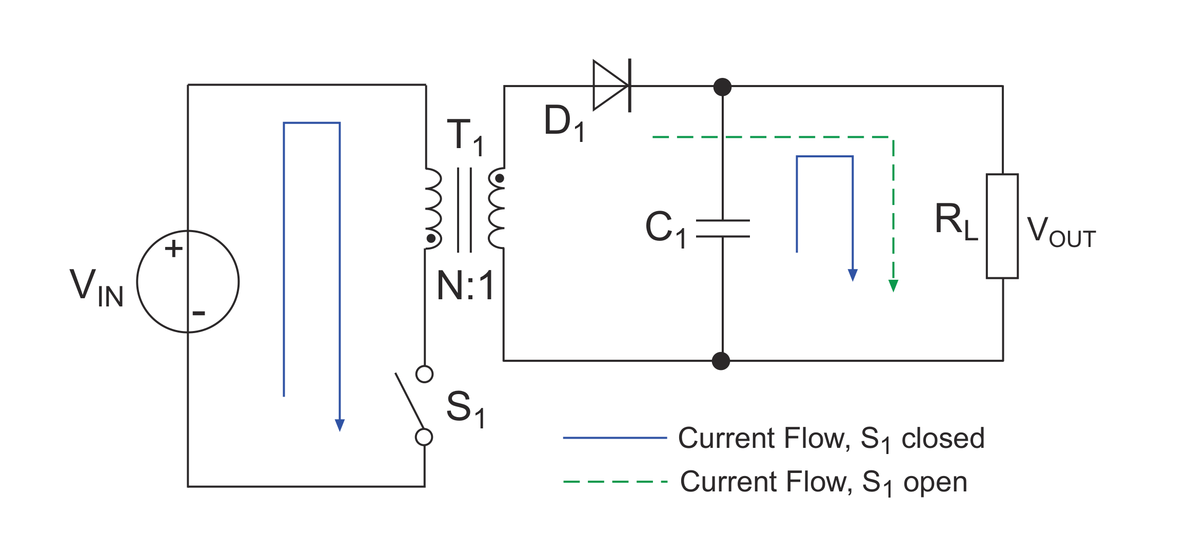
Note: The switch \(S_1\) in the diagram is actually an electronic switch (such as a power MOSFET), but for the sake of simplicity, it is simplified as a regular switch here.
Basic principle:
- Switch \(S_1\) closed (solid blue line)
- At this time, a loop is formed on the primary side of transformer \(T_1\), and the current \(I_{S1}\) flowing through the primary inductance \(L_P\) increases at a rate of \(\frac{V_{in}}{L_P}\). At this time, no current flows through the secondary winding inductance \(L_S\) to the load, and the load current is provided by the capacitor \(C_1\).
- The energy input to the transformer at this time is: \(\frac{V_{in}*t_{on}}{N}\) (where N is the turns ratio).
- Switch \(S_1\) opened (dashed green line)
- At this time, due to the collapse of the magnetic field in transformer \(T_1\), the voltages in the primary and secondary windings are reversed, and the energy stored in the primary winding is transferred to the secondary winding. During the transfer process, the voltage in the secondary winding rises rapidly, accompanied by a pulse current that decreases at a rate of \(\frac{V_{out}}{L_S}\), and supplies power to the load and charges the capacitor \(C_1\). Diode \(D_1\) acts as a peak rectifier here.
- The energy output from the transformer at this time is: \(V_{out}*t_{off}\)
Because the energy transfer of the transformer is conserved, \(\frac{V_{in}*t_{on}}{N}=V_{out}*t_{off}\), we can obtain:
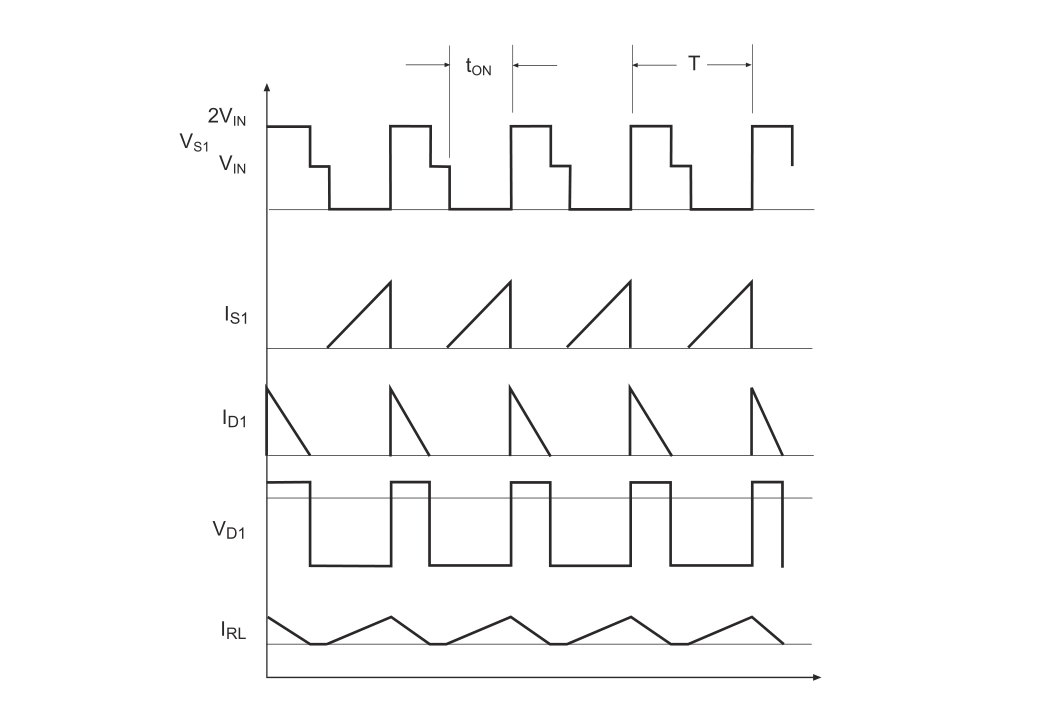
Waveforms at each node:
It can be observed that the flyback and buck-boost transfer formulas differ only by a coefficient of 1/N. The advantage of flyback is that the output voltage can be adjusted to a high level when the duty cycle is very small, making it suitable for power supplies with high output voltage. Additionally, multiple secondary windings can be added to achieve multiple outputs with different polarities, making it suitable for low-cost designs.
The disadvantages of flyback are that the selection of the transformer core with an air gap should be done carefully to avoid saturation, as severe hysteresis can significantly reduce the efficiency of the transformer. In addition, the high peak current and eddy current losses in the windings are also issues. These two problems limit the practical operating frequency range of flyback. Finally, when S1 is opened, a large inductive spike will appear on the primary winding, which will put a lot of pressure on the switch MOSFET.
Forward
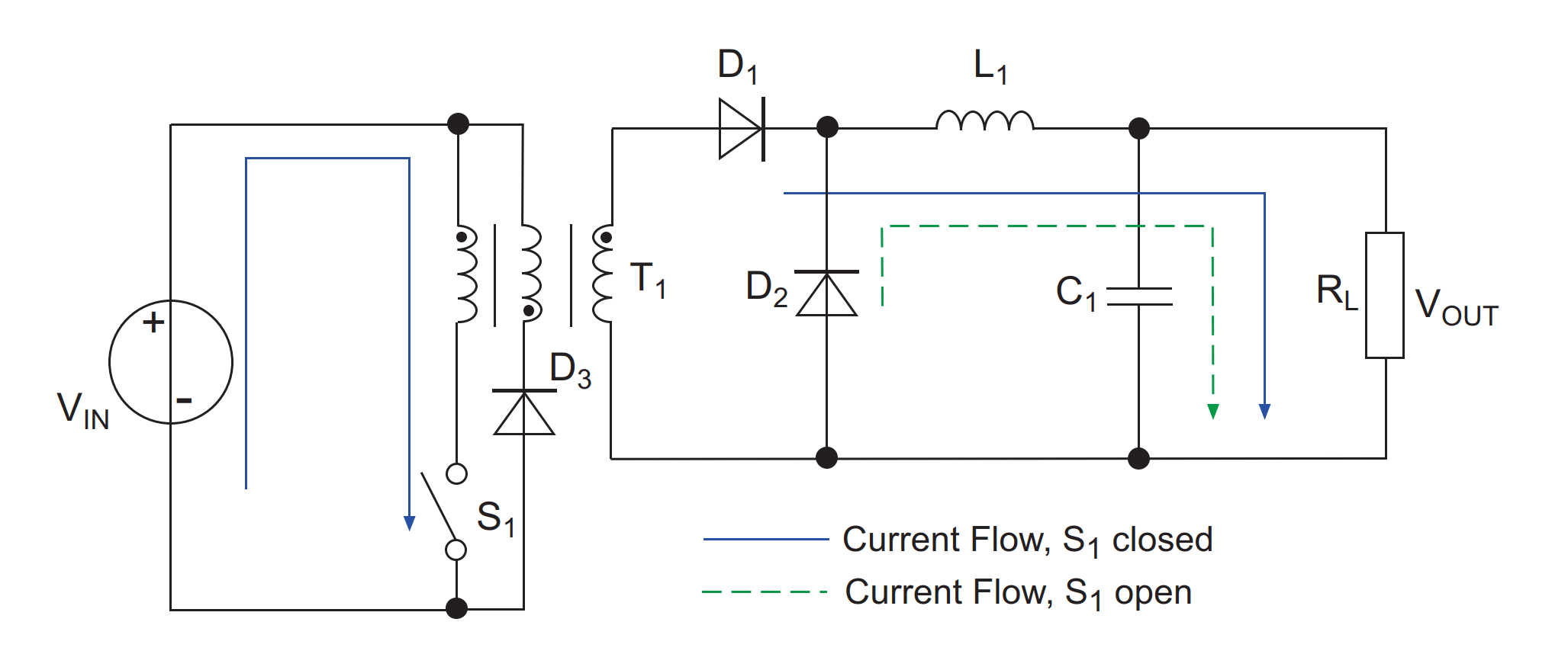
The forward converter can generate a stable output voltage based on the function of the turns ratio. The topology diagram is as follows:
Basic principle:
Translate into English:
- Close switch \(S_1\) (solid blue line)
- At this time, a loop is formed on the primary side of transformer \(T_1\), and the current \(I_{S1}\) flowing through the primary winding inductance \(L_P\) increases at a rate of \(\frac{V_{in}}{L_P}\). Since the primary and secondary windings are coupled, an increase in current in the primary winding will induce a current in the secondary winding. The induced voltage at the ends of the secondary winding is \(\frac{V_{in}}{N}\). The current in the secondary winding increases at a rate of \(\frac{V_{in}}{L_1 N}\) and ultimately powers the load \(R_L\) and output capacitor \(C_1\) through rectifying diode \(D_1\) and output inductance \(L_1\).
- The energy input to the transformer at this time is: \((\frac{V_{in}}{N}-V_{out})\cdot t_{on}\) (where N is the turns ratio).
- Open switch \(S_1\) (dashed green line)
- When the voltage across capacitor \(C_1\) gradually rises to the upper threshold, a "turn-off" feedback signal is generated (usually implemented by an optocoupler), causing switch \(S_1\) to open and interrupt the current supply from the source. At this time, the reset winding and diode \(D_3\) together maintain the magnetic field in the transformer without disappearing (but also causing the current to decrease at a rate of \(\frac{V_{in}}{L_P}\)). The voltage at the ends of the secondary winding will reverse polarity, and the reverse current will decrease at a rate of \(\frac{V_{out}}{L_1}\), and then power the load \(R_L\) and output capacitor \(C_1\) through freewheeling diode \(D_2\) and inductance \(L_1\). When the voltage across \(C_1\) decreases to the threshold, a "turn-on" feedback signal is generated to close \(S_1\) again and start a new cycle.
- The energy output from the transformer at this time is: \(V_{out}\cdot t_{off}\)
According to the principle of energy conservation in transformers, \((\frac{V_{in}}{N}-V_{out})*t_{on}=V_{out}\cdot t_{off}\), we can obtain:
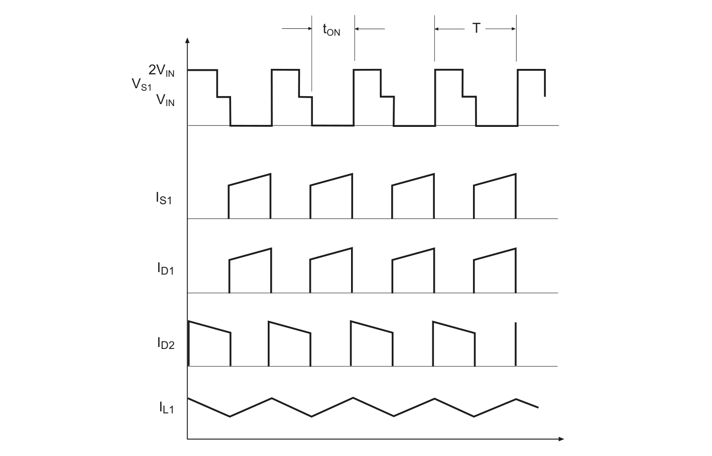
Waveform curves at each node:
The difference compared to Flyback is that Forward continuously transfers energy from the primary to the secondary side of the transformer without storing energy in the air gap of the magnetic core. As a result, the magnetic core no longer requires an air gap, which in turn eliminates losses and EMI radiation. Since hysteresis loss is no longer a serious problem in Forward, the inductance of the magnetic core can be large, and the peak current can be reduced accordingly. This further reduces losses in the windings and diodes, as well as the ripple current in the input and output.
Therefore, for the same output power, Forward is more efficient than Flyback. However, the disadvantage is that the cost is relatively high, and a minimum load needs to be set to prevent entering discontinuous mode, because the energy transfer is completely different in discontinuous mode.
Active Clamp
🚧
Push-Pull
🚧
References and Acknowledgements
- Switching Power Supply Basics
- Introduction to Buck, Boost, and Buck-Boost Converters
- "Principles and Design of Switching Power Supplies"
- "DC-DC Converter Handbook and Practical Tips for Users"
Original: https://wiki-power.com/
This post is protected by CC BY-NC-SA 4.0 agreement, should be reproduced with attribution.This post is translated using ChatGPT, please feedback if any omissions.