Test Interface and TIC Basics
In semiconductor testing, the TIC (Test Interface Controller) is a bus master controller that follows the Test Interface protocol specified in the AMBA (Advanced Microcontroller Bus Architecture) specification. AMBA is an on-chip communication standard for embedded microcontrollers, encompassing three bus protocols:
- AHB (the Advanced High-performance Bus)
- ASB (the Advanced System Bus)
- APB (the Advanced Peripheral Bus)
The concept of AMBA is to isolate the testing of individual modules in a system, with each module's testing relying solely on the bus interface. A testing method is needed to test the input and output of peripherals not connected to the bus.
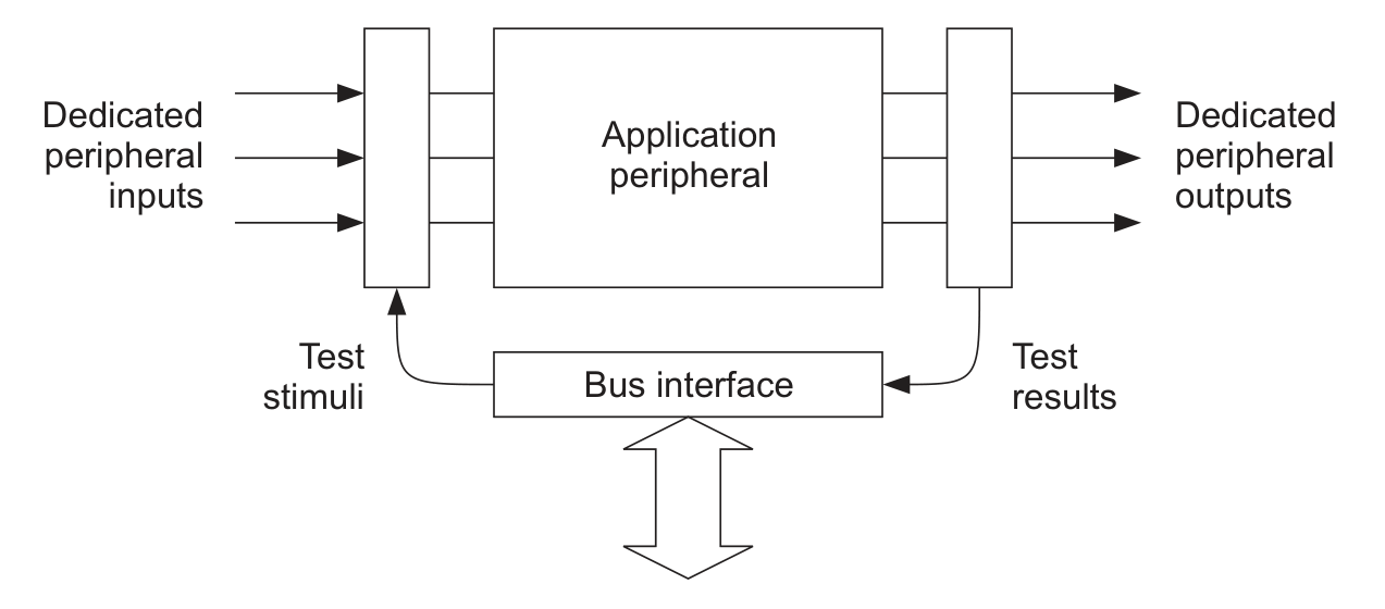
This testing method can be achieved through the Test Interface. It uses a simple three-wire handshake mechanism to control the read and write of vectors. Additionally, it utilizes the EBI (External Bus Interface) as the data path to import external vectors into the internal bus.
Test Interface Pins
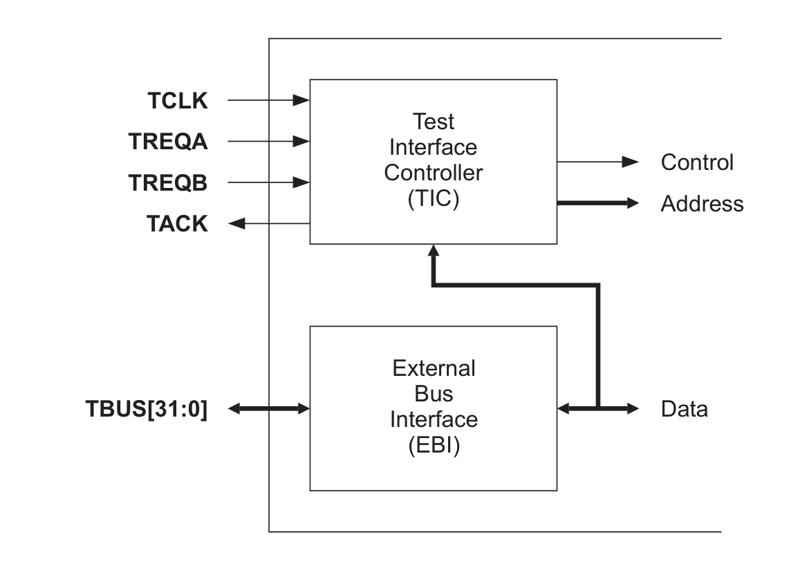
As shown in the above diagram, the Test Interface pins consist of three parts:
- A clock pin TCLK
- Three control pins TREQA, TREQB, and TACK
- A 32-bit test bus TBUS[31:0]
In the minimal configuration, the Test Interface only requires TREQA and TACK as dedicated pins for controlling the entry and exit of the test mode. Other pins can be implemented by reusing pins on the device.
TREQA/TREQB (Test Bus Request) are input signals. During normal system operation, TREQA is used to request entry into the test mode, allowing vectors to be loaded. During the testing process, TREQA is used together with TREQB to indicate the type of vector to be used in the next cycle.
TACK (Test Bus Acknowledge) is an output signal used to indicate the state of the bus and when a test item is completed. When TACK is low, it indicates that the current vector needs more time until TACK becomes high. Only when TACK is high, TREQA/TREQB will read external control signals.
TCLK (Test Clock) is a clock signal input. The test clock for the Test Interface is provided externally. When switching between normal mode and test mode, it is required that the TCLK clock has no glitches.
TBUS[31:0] (Test Bus) is a 32-bit bidirectional test interface bus. In the input state, it is used to transmit Vector Address, Control information, and perform Write operations. In the output state, it can be used to perform Read operations. When a change in the TBUS input/output state is required, the test bus protocol ensures the provision of a cycle for switching.
When the system is operating normally, the Test Interface is controlled by a three-wire truth table as follows:
| TREQA | TREQB | TACK | Status |
|---|---|---|---|
| 0 | 0 | 0 | Normal operation, not in test mode |
| 1 | 0 | 0 | Request to enter test mode |
| 0 | 1 | 0 | Reserved for external host request |
| - | - | 1 | Entered test mode |
Initially, TREQA is at a low level, indicating that it has not entered test mode. When TREQA is set to a high level, a request to enter test mode is made. Then, when TACK outputs a high level, it indicates that TIC allows entering test mode. At this time, TCLK becomes the internal clock source. Once in test mode, the values on the three lines and their corresponding system states are as follows:
| TREQA | TREQB | TACK | Status |
|---|---|---|---|
| - | - | 0 | Current operation not yet completed |
| 1 | 1 | 1 | Address/Control/TurnAround Vector |
| 1 | 0 | 1 | Write Test Vector |
| 0 | 1 | 1 | Read Test Vector |
| 0 | 0 | 1 | Exit test mode |
Next, TREQB can be set to a high level to load the Address Vector. Then, read and write operations can be performed. When exiting test mode, an Address Vector should be passed first to ensure that all internal transfers have been completed. Then, set both TREQA and TREQB to a low level to indicate exiting test mode. Finally, TACK will output a low level to indicate that test mode has been exited.
Types of Vectors
In the Test Interface, there are 5 types of Vectors:
- Address Vector: Vector that declares an address
- Write Test Vector: Vector for writing (0/1)
- Read Test Vector: Vector for reading (L/H)
- Control Vector: Vector for control
- TurnAround Vector: Vector for changing direction
The triggering of Address/Control/TurnAround Vectors is determined by the common values of TREQA/TREQB. To determine the type of Vector, the following rules can be followed:
- If only a single Address/Control/TurnAround Vector appears, it is an Address Vector.
- If a continuous sequence of Address/Control/TurnAround Vectors appears, with the last one being a Control Vector, all the others are Address Vectors.
- After one or more Read Vectors, there will always be a TurnAround Vector. (In ASB, it is a single one, while in AHB, two are needed)
In addition, Burst Vector is a concatenation of multiple Write/Read Test Vectors (note that they are of the same type, not mixed). This allows applying the Address only once, which improves testing speed. This Address can either be kept static (all Vectors use the same initial Address passed in) or incremented (depending on whether the TIC has an enabled Address incrementer). In the absence of an incrementer, a static Address will be used by default.
Address Vector
Before any Read/Write operation, the Address Vector must be passed. It follows the following rules:
- Both TREQA/TREQB must be set to 1 to indicate that the next cycle is the Address Vector.
- In the next cycle, the Address is loaded onto TBUS[31:0]. At this time, the values on TREQA/TREQB will jointly determine the state of the next cycle.
In some high-speed signal systems, it may be necessary to continuously load multiple Address Vectors (allowing enough time for the Address to be transferred from the external to the internal Address bus). In this case, TIC will force the loading of the second Address Vector Cycle by setting the TACK output of the first Address Vector to 0.
Control Vector
The Control Vector always follows a single or a series of Address Vectors. It is used to update the Control information inside TIC. It follows the following rules:
- Both TREQA/TREQB must be set to 1 to indicate that the next cycle is the Address Vector.
- In the next cycle, the Address is loaded onto TBUS[31:0]. At this time, both TREQA/TREQB are still set to 1, and the Control Vector will appear in the next cycle.
- In the next cycle, the Control information will be loaded onto TBUS[31:0]. At this time, the values on TREQA/TREQB will determine the state of the next cycle.
If an invalid Control Vector needs to be set, the 0th bit can be set to 0, so that the information of the Control Vector can be preserved but not applied.
Write Test Vector
After successfully entering the test mode and specifying the Address, Read/Write operations can be performed. The Address used for Write operations is defined by the preceding Address Vector. The Write Test Vector can follow the following Vectors:
- A single Address Vector.
- A sequence of Address/Control Vectors.
- Another Write Test Vector, forming a Write Burst.
- TurnAround Vector after a single/multiple Read operations.
When the transfer state needs to be delayed, TACK will go low. During this waiting time, TREQA/TREQB needs to change to specify the type of the next Vector, but the Write operation performed on TBUS[31:0] should still continue, and no Read operation should be performed at this time.
Read Test Vector
Similar to the Write Test Vector, the Address used for Read operations depends on the preceding Vectors. The Read Test Vector can follow the following Vectors:
- A single Address Vector.
- A sequence of Address/Control Vectors.
- Another Read Test Vector, forming a Read Burst.
- Single/multiple Write operations.
After a single or multiple Read operations, there must always be a TurnAround Vector to prevent bus conflicts with the external TBUS signal.
TurnAround Vector
The TurnAround Vector can be used to switch the direction of TBUS transfer between Write and Read operations. It is necessary to insert a TurnAround Vector when Read operations change to Write operations. This operation does not write a new Address.
The above is some basic knowledge about the Test Interface and TIC. For specific operation of TIC on AHB, please refer to the next article TIC on AHB (in progress...).
References and Acknowledgements
- IHI0011 - ARM advanced microcontroller bus architecture (AMBA) specification.Rev 2.0
Original: https://wiki-power.com/ This post is protected by CC BY-NC-SA 4.0 agreement, should be reproduced with attribution.
This post is translated using ChatGPT, please feedback if any omissions.